Download
1 / 21
210 likes | 216 Views
Learn how to expand the number of output and input lines using the LPT port and expansion slots on your computer. This guide provides circuit diagrams, information on different expansion slots, and software testing tools using C#.

E N D
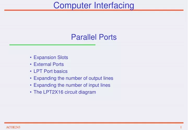
Computer Interfacing Parallel Ports Expansion Slots External Ports LPT Port basics Expanding the number of output lines Expanding the number of input lines The LPT2X16 circuit diagram
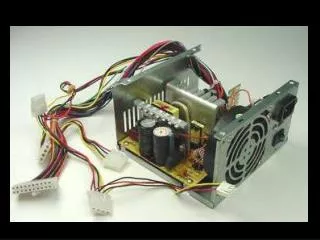
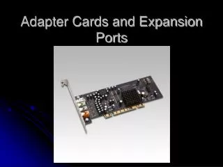
Expansion Slots • Slots/Connectors located on the motherboard that allow the connection of expansion hardware cards on the computer. Typical cards are modems, video cards, sound cards, as well as special purpose cards such as automation and data acquisition cards. • Expansion slots can be general purpose • ISA (Industry Standard Architecture): Introduced by IBM with the first personal computers (IBM-XT as an 8-bit computer bus and IBM-AT as a 16-bit computer bus) • Now is obsolete, but there are ISA-based peripherals still in use. • EISA (Extended Industry Standard Architecture): Introduced in 1988 for IBM compatible 32-bit computers used with the 80386, 80486 and Pentium microprocessors. • Now obsolete – It was not successful due to the use of the superior PCI standard • PCI (Peripheral Component Interconnect): Introduced by Intel in 1992 as a 32-bit/64-bit (133Mbps) bus. • It has been replaced by the PCI Express, the PCI-X (1/4/..) and PCI-e slots • Expansion slots can also be special purpose (AGP for video cards, or IDE and SATA for disk drives)
ISA (Industry Standard Architecture) • There are two versions of the ISA expansion slot • The 8-bit and the16-bit • Signal definitions are almost identical to the signals (pins) of the 8086 microprocessor, • The ISA cards were initially configured by the end-user by setting jumpers and dip switches accordingly. • Configuration was related with the addresses occupied by the I/O ports and the memory of the card, the interrupts and the direct memory access (DMA) channels. • In 1993 Intel and Microsoft introduced the Plug-and-Play (PnP) ISA card where the computer could automatically detect and setup the configuration of the card.
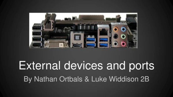
The LPT port Registers • The LPT port has three registers: • Data Register (Address 888): • Eight output lines • Status Register (Address 889): • Six input lines (two internally inverted) • Control Register (Address 890): • Six output lines (two internally inverted)
LPT Port Testing Software Software developed in C# using the “inpout32.dll” Use 8 buttons to toggle (change from 1 to 0 of from 0 to 1) each bit of the data to be send to the Data Register The number formed is displayed on the screen in decimal form Data is send to the Data Register by clicking on the “Data Out” button Use 8 buttons to toggle (change from 1 to 0 of from 0 to 1) each bit of the data to be send to the Control Register Data is send to the Control Register by clicking on the “Control Out” button Use of a timer that reads the Status Register every 100ms and display the state of each bit on 8 labels
The GUI of the LPT Tester program ButtonDataD7 ButtonDataD0 LabelData ButtonDataOut LabelStatusD0 LabelStatusD7 ButtonControlD7 ButtonControlD0 ButtonDataOut
Using unmanaged dll libraries in C# • using System; • ………… • using System.Windows.Forms; • using System.Runtime.InteropServices; • namespace LPT_Test • { • public partial class FormMain : Form • { • ……….//Variable declarations • public FormMain() • { • InitializeComponent(); • } • ……….// Insert program code here • public class PortAccess • { • [DllImport("inpout32.dll", EntryPoint = "Inp32")] • public static extern short Inp32(short PortAddress); • [DllImport("inpout32.dll", EntryPoint = "Out32")] • public static extern void Out32(short PortAddress, int data); • } • } Needed for DllImport Name of “.dll” file needed. Must be copied in the folder of the “.exe” file. Prototype of “Inp32” function Code needed to specify the dll file (inpout32.dll) file and the functions (Inp32) and (Out32)
Testing the output data port • public partial class FormMain : Form • { • int dval = 0; • int cval = 0x0b; • public FormMain() • { • InitializeComponent(); • } • private void ButtonDataD7_Click(object sender, EventArgs e) • { • if (ButtonDataD7.Text == "0") • { • ButtonDataD7.Text = "1"; • dval = dval + 128; • LabelData.Text = dval.ToString(); • } • else • { • ButtonDataD7.Text = "0"; • dval = dval - 128; • LabelData.Text = dval.ToString(); • } • ……… Declare global variables Code executed when clicking on the button “ButtonDataD7” If “0” then switch to “1” and add 128 on “dval” (D7=128) If “1” then switch to “0” and subtract 128 from “dval” (D7=128)
Testing the output data port (Continued) • private void ButtonDataD6_Click(object sender, EventArgs e) • { • if (ButtonDataD6.Text == "0") • { • ButtonDataD6.Text = "1"; • dval = dval + 64; • LabelData.Text = dval.ToString(); • } • else • { • ButtonDataD6.Text = "0"; • dval = dval - 64; • LabelData.Text = dval.ToString(); • } • } • private void ButtonDataD5_Click(object sender, EventArgs e) • { • if (ButtonDataD5.Text == "0") • { • ButtonDataD5.Text = "1"; • dval = dval + 32; • LabelData.Text = dval.ToString(); • }……… If “0” then switch to “1” and add 64 on “dval” (D6=64) If “1” then switch to “0” and subtract 64 from “dval” (D6=64) If “0” then switch to “1” and add 32 on “dval” (D5=32)
Testing the output Control port • private void ButtonControlD4_Click(object sender, EventArgs e) • { • if (ButtonControlD4.Text == "0") • { • ButtonControlD4.Text = "1"; • cval = cval + 16; • } • else • { • ButtonControlD4.Text = "0"; • cval = cval - 16; • } • } • private void ButtonControlD3_Click(object sender, EventArgs e) • { • if (ButtonControlD3.Text == "0") • { • ButtonControlD3.Text = "1"; • cval = cval - 8; • } • else • { • ButtonControlD3.Text = "0"; • cval = cval + 8; • } • } ……… If “0” then switch to “1” and add 16 on “eval” (D4=16) If “1” then switch to “0” and subtract 16 from “eval” (D6=16) If “0” then switch to “1” and subtract 8 on “eval” (D3=8) Note: #(sel) is inverted If “1” then switch to “0” and add 8 on “eval” (D3=8) Note: #(sel) is inverted
Output to the Data and Control ports • private void ButtonDataOut_Click(object sender, EventArgs e) • { • PortAccess.Out32(888, dval); • } • private void ButtonControlOut_Click_1(object sender, EventArgs e) • { • PortAccess.Out32(890, cval); • } Output “dval” to the LPT Data Port (address 888) Output “eval” to the LPT Control Port (address 890)
Testing the input Status port • private void timer1_Tick(object sender, EventArgs e) • { • short sval = PortAccess.Inp32(889); • if ((sval & 0x80)==0) LabelStatusD7.Text = "1"; • else LabelStatusD7.Text = "0"; • if ((sval & 0x40)!=0) LabelStatusD6.Text = "1"; • else LabelStatusD6.Text = "0"; • if ((sval & 0x20)!=0) LabelStatusD5.Text = "1"; • else LabelStatusD5.Text = "0"; • if ((sval & 0x10)!=0) LabelStatusD4.Text = "1"; • else LabelStatusD4.Text = "0"; • if ((sval & 0x08)!=0) LabelStatusD3.Text = "1"; • else LabelStatusD3.Text = "0"; • if ((sval & 0x04)==0) LabelStatusD2.Text = "1"; • else LabelStatusD2.Text = "0"; • if ((sval & 0x02)!=0) LabelStatusD1.Text = "1"; • else LabelStatusD1.Text = "0"; • if ((sval & 0x01) != 0) LabelStatusD0.Text = "1"; • else LabelStatusD0.Text = "0"; • }
Computer Interfacing LPT 2x16 board circuit
Expanding the number of output lines Printer Port ( D : 888 , S : 889 , C : 890 ) C 0 ' Strobe ( 1 ) C 1 ' Auto ( 14 ) + 5 V OE ' Vcc D Q D 0 D 0 ( 2 ) DO 1 . 0 1 1 D Q D 1 D 1 ( 3 ) DO 1 . 1 2 2 7 D Q 4 D 2 D 2 ( 4 ) DO 1 . 2 3 3 H D Q D 3 D 3 ( 5 ) DO 1 . 3 4 4 C T D Q D 4 D 4 ( 6 ) DO 1 . 4 5 5 5 7 D Q D 5 D 5 ( 7 ) DO 1 . 5 6 6 4 D Q D 6 D 6 ( 8 ) DO 1 . 6 7 7 D Q D 7 D 7 ( 9 ) DO 1 . 7 8 8 Gnd EN S 6 Ack ( 10 ) S 7 ' Busy ( 11 ) + 5 V OE ' S 5 Paper ( 12 ) Vcc D Q S 4 Select ( 13 ) DO 0 . 0 1 1 D Q DO 0 . 1 2 2 7 D Q C 2 Init ( 16 ) 4 DO 0 . 2 3 3 H D Q C 3 ' SelectIn ( 17 ) DO 0 . 3 4 4 C T D Q DO 0 . 4 5 5 5 ( 18 .. 25 ) 7 D Q DO 0 . 5 6 6 4 D Q DO 0 . 6 7 7 D Q DO 0 . 7 8 8 Gnd EN void OutPort(short index, short value) { Out32(888,value); Out32(890,0); if (index==1) Out32(890,0x1); if (index==2) Out32(890,0x2); Out32(890,0); }
Expanding the number of input lines short InPort(short index) { short int temp2 = 0; short int x; Out32(890,0x0c); x=Inp32(889); if ((x & 0x10) !=0) temp2=temp2+128; if ((x & 0x20) !=0) temp2=temp2+32; if ((x & 0x40) !=0) temp2=temp2+2; if ((x & 0x80) ==0) temp2=temp2+8; Out32(890,0x04); x=Inp32(889); if ((x & 0x10) !=0) temp2=temp2+64; if ((x & 0x20) !=0) temp2=temp2+16; if ((x & 0x40) !=0) temp2=temp2+1; if ((x & 0x80) ==0) temp2=temp2+4; return temp2; }