Download
1 / 23
350 likes | 2.11k Views
PML and Master Slave Boundary Conditions. Advanced Boundary Conditions. This section looks at two different types of advanced boundary conditions available in HFSS: Perfectly Matched Layers (PMLs) Periodic boundary conditions – Master and Slave boundaries. Perfectly Matched Layer (PML).

E N D
Advanced Boundary Conditions • This section looks at two different types of advanced boundary conditions available in HFSS: • Perfectly Matched Layers (PMLs) • Periodic boundary conditions – Master and Slave boundaries.
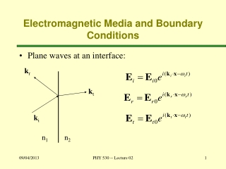
Perfectly Matched Layer (PML) • What are Perfectly Matched Layers? • Perfectly Matched Layers (PMLs) are fictitious materials that fully absorb the electromagnetic fields acting upon them. • There are two types of PML applications: “free space termination” and “reflection-free termination” of guided waves. • In free space termination, all PML objects must be included in a surface that radiates into free space equally in every direction. PMLs can be superior to radiation boundaries in this case because PMLs enable radiation surfaces to be located closer to radiating objects, reducing the problem domain. Any homogenous isotropic material, including lossy materials such as ocean water, can surround the model. • In reflection-free termination of guided waves, the structure continues uniformly to infinity. The termination surface of the structure radiates in the direction in which the wave is guided. Reflection-free PMLs are superior to free space or radiation boundary terminations in this kind of application. Reflection-free PMLs are also superior for simulating phased array antennas because the antenna radiates in a certain direction.
Perfectly Matched Layer (PML) • Implementation in HFSS • HFSS uses an adaptive PML: • In “classic” implementation, one needs several layers, one over the other, to achieve desired attenuation. • With adaptive PML, one layer is enough. • Adaptive meshing takes care of the rest. • Advantages: • Easier implementation. • More robust. • Smaller mesh. • HFSS contains a PML setup wizard for: • Perfectly Matched Layer object creation. • Material creation and assignment. • PML boundaries can also be set-up manually. • HFSS automatically identifies PML objects by a naming convention: • Any object with a name beginning with the letters ‘PML’ is identified as a PML and is subject to: • special adaptive meshing. • incident-wave treatment. • user-defined radiation surfaces during post processing.
Perfectly Matched Layer (PML) • Radiation boundary versus PML • Radiation Boundary Condition • Sensitive to the incident angle, less accurate for non-normal incidence. • Fully automatic. • Easy to use. • Radiation boundaries need to be placed around l/4 away from radiating objects. • Perfectly Matched Layer (PML) • Accurate, boundary has zero reflection. • A “fictitious” biaxial anisotropic material. • Reasonably automatic to create using PML setup wizard. • More accurate for calculating radiation parameters. • PMLs can be brought much closer to radiating objects (as close as l/10), resulting in a smaller problem space and smaller mesh.
Perfectly Matched Layer (PML) • Automatic PML creation • Three basic steps: • Create device objects. • Select surfaces for PML objects to be created on. (note you may want to create a face list at this point for post processing later on. This can be done using 3D Modeler > List > Create > Face List.) • Launch PML setup wizard: Here radiation is allowed through three faces.Two other faces will later be assigned symmetry boundaries.
Perfectly Matched Layer (PML) • Automatic PML creation, continued. • PML setup wizard has a two step process, firstly creating the PML cover objects: Specify layer thicknesses – normally set this to be /4 of the lowest frequency to be solved for
Perfectly Matched Layer (PML) • Automatic PML creation, continued. • PML cover is added to the box on all radiation surfaces:
Perfectly Matched Layer (PML) • Automatic PML creation, continued. • Secondly defining the PML material properties: • Note for this problem the fields radiate equally in free space in all directions hence ‘PML Objects Accept Free Radiation’ is selected. Set minimum frequency to be solved in problem Minimum radiating distance is the minimum distance between the boundary and any radiating object.
Perfectly Matched Layer (PML) • The PML setup wizard: • Automatically creates PML materials. • Automatically calculates PML material matrices. • PML material properties are automatically assigned to the cover objects using default names.
Open-ended waveguide results Magnitude of S11 of an open-ended waveguide. Note that the boundary PML is closer to aperture than the radiation boundary and requires fewer tetrahedra for better accuracy. Mesh of an open-ended waveguide The non-uniform PML mesh is evident. Perfectly Matched Layer (PML) PML: d/l=0.15, 1782 tetrahedra ABC: d/l=0.32, 6736 tetrahedra
Creating PMLs manually The PML setup wizard can only create rectangular PML objects. If another shape of PML object is required (e.g. to terminate a circular waveguide) then PMLs must be created manually: Perfectly Matched Layer (PML) Draw the PML object at the radiation surface, and then select it. Give the object a name with the prefix PML. Object names that start with PML are necessary for HFSS to recognize them as PMLs.
Creating PMLs manually, cont. Launch the PML setup wizard. Perfectly Matched Layer (PML) Select use selected object as PML cover. Choose the corresponding base object. Enter the thickness of the PML layer object. Select the orientation of the PML object in terms of the direction of outward propagation – in this case radiation would be in the y-direction.
Creating PMLs manually, cont As this is a waveguide termination, ‘PML Objects Continue Guided Wave’ option is selected. The propagation constant at the minimum frequency must then be entered. The minimum radiating distance is specified as before. Once completed the summary box will appear as for the automatic PML creation (see page 10). Perfectly Matched Layer (PML)
Post processing Far Field data with PMLs To insert a far field setup where a PML has been used, you need to first create a face list of the radiating surfaces (note sometimes it is easier to create this when you first select the faces for creating the PML objects): Perfectly Matched Layer (PML)
Post processing Far Field data with PMLs This list appears in the ‘lists’ section of the model tree. When you create a far field radiation setup, under the ‘Radiation Surface’ tab select ‘Use Custom Radiation Surface’ and select this face list from the drop down menu. Perfectly Matched Layer (PML)
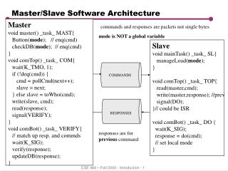
Master and Slave Boundary Conditions • Master and Slave Boundaries • Master and slave boundaries enable you to model planes of periodicity where the E-field on one surface matches the E-field on another to within a phase difference. They force the E-field at each point on the slave boundary match the E-field to within a phase difference at each corresponding point on the master boundary. They are useful for simulating devices such as infinite arrays. • Unlike symmetry boundaries, E does not have to be tangential or normal to these boundaries. The only condition is that the fields on the two boundaries must have the same magnitude and direction (or the same magnitude and opposite directions). • When creating matching boundaries, keep the following points in mind: • Master and slave boundaries can only be assigned to planar surfaces. These may be the faces of 2D or 3D objects. • The geometry of the surface on one boundary must match the geometry on the surface of the other boundary. For example, if the master is a rectangular surface, the slave must be a rectangular surface of the same size. • If the mesh on the master boundary does not match the mesh on the slave boundary exactly, the solution will fail. Normally HFSS automatically forces the mesh to match on each boundary; however, in some cases, the mesh cannot be forced to match. To prevent the solution from failing, create a virtual object on the slave boundary that exactly matches any extra object on the master boundary, or create a virtual object on the master boundary that exactly matches any extra object on the slave boundary.
Master and Slave Boundary Conditions • Master and Slave Boundaries • To make a surface a master or slave boundary, you must specify a coordinate system that defines the plane on which the selected surface exists. When HFSS attempts to match the two boundaries, the two coordinate systems must also match each other. If they do not, HFSS will transpose the slave boundary to match the master boundary. When doing this, the surface to which the slave boundary is assigned is also transposed. If, after doing this, the two surfaces do not occupy the same position relative to their combined defined coordinate system, an error message appears. • For example, consider the following figure: • To match the coordinate system of the master boundary, the coordinate system on the slave boundary must rotate 90 degrees counterclockwise; however, when this is done, you get the following: • The two surfaces do not correspond and thus the mesh will not match, causing an error message. • The angle between the axes defined by the u point and v point must be identical for the master and slave boundary.
Master and Slave Boundary Conditions • Assigning Master boundary Ensure plane is set to that of desired face Select face for master boundary and launch master boundary assignment Under Coordinate system select new vector to assign U
Master and Slave Boundary Conditions • Assigning Master boundary Note reverse direction changes orientation of V with respect to U
Master and Slave Boundary Conditions • Assigning Slave boundary Ensure plane is set to that of desired face Select face for slave boundary and launch slave boundary assignment Select Master boundary slave is associated with
Master and Slave Boundary Conditions • Assigning Slave boundary Define directions for U and V on slave boundary – remember these must match the Master boundary assignment
Master and Slave Boundary Conditions • Assigning Slave boundary • You have the option to relate the slave boundary’s E-fields to the master boundary’s E-fields in one of the following ways: • Select Scan Angles, and then enter the f scan angle in the Phi box and the q scan angle in the Theta box. The phase delay is calculated from the scan angles; however, if you know the phase delay, you may enter it directly in the Phase Difference box below. • Select Field Radiation, and then enter the phase difference, or phase delay, between the boundaries’ E-fields in the Phase Difference box.