Download
1 / 54
540 likes | 653 Views
E. De Lucia LNF-INFN. Development of CGEM technology for ultra-light tracking detectors . June 4 th 2013 Jagiellonian University Krakow. KLOE at DAFNE f -factory. Frascati φ - factory DA φ NE : an e + e - collider @ √s =1019.4 MeV = M φ Best performance in 2005:

E N D
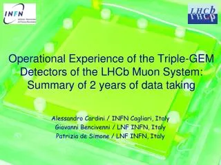
E. De Lucia LNF-INFN Development of CGEM technology for ultra-light tracking detectors June 4th 2013 Jagiellonian University Krakow
KLOE at DAFNE f-factory • Frascati φ-factoryDAφNE: ane+e- collider @ √s =1019.4 MeV = Mφ • Best performance in 2005: • Lpeak= 1.4 × 1032 cm-2s-1 • ∫ Ldt = 8.5 pb-1/day • KLOE has acquired 2.5 fb-1 @ √s=Mφ (2001-05) • + 250 pb-1off-peak @ √s=1 GeV Precision Kaon and Hadron Physics with KLOE Rivista del Nuovo Cimento Vol.31, N.10 (2008) Erika De Lucia -- Symposium at Jagiellonian University, June 04 2013 Krakow
KLOE at DAFNE f-factory • Frascati φ-factoryDAφNE: ane+e- collider @ √s =1019.4 MeV = Mφ • Best performance in 2005: • Lpeak= 1.4 × 1032 cm-2s-1 • ∫ Ldt = 8.5 pb-1/day • KLOE has acquired 2.5 fb-1 @ √s=Mφ (2001-05) • + 250 pb-1off-peak @ √s=1 GeV Precision Kaon and Hadron Physics with KLOE Rivista del Nuovo Cimento Vol.31, N.10 (2008) Erika De Lucia -- Symposium at Jagiellonian University, June 04 2013 Krakow
7m 6 m KLOE at DAFNE f-factory F KS KL • Lead/scintillating fiber • 98% coverage of solid angle • 88 modules (barrel + end-caps) • 4880 PMTs (two side read-out) • 4 m diameter × 3.3 m length • 90% helium, 10% isobutane • 12582/52140 sense/tot wires • All-stereo geometry KS = 0.6 cmKL = 340 cm K = 95 cm Drift Chamber Electromagnetic Calorimeter sE /E = 5.4%/ st = 54 ps/ srf= 150 mm sz = 2 mm sV = 3 mm sp /p = 0.4 % • 50 ps(calib) B = 0.52 T Erika De Lucia -- Symposium at Jagiellonian University, June 04 2013 Krakow
7m 6 m KLOE at DAFNE f-factory F KS KL • Lead/scintillating fiber • 98% coverage of solid angle • 88 modules (barrel + end-caps) • 4880 PMTs (two side read-out) • 4 m diameter × 3.3 m length • 90% helium, 10% isobutane • 12582/52140 sense/tot wires • All-stereo geometry KS = 0.6 cmKL = 340 cm K = 95 cm Drift Chamber Electromagnetic Calorimeter sE /E = 5.4%/ st = 54 ps/ srf= 150 mm sz = 2 mm sV = 3 mm sp /p = 0.4 % • 50 ps(calib) B = 0.52 T Erika De Lucia -- Symposium at Jagiellonian University, June 04 2013 Krakow
7m 6 m KLOE at DAFNE f-factory F KS KL • Lead/scintillating fiber • 98% coverage of solid angle • 88 modules (barrel + end-caps) • 4880 PMTs (two side read-out) • 4 m diameter × 3.3 m length • 90% helium, 10% isobutane • 12582/52140 sense/tot wires • All-stereo geometry KS = 0.6 cmKL = 340 cm K = 95 cm Drift Chamber KL in Calorimeter KS 00 Electromagnetic Calorimeter sE /E = 5.4%/ st = 54 ps/ srf= 150 mm sz = 2 mm sV = 3 mm sp /p = 0.4 % • 50 ps(calib) B = 0.52 T Erika De Lucia -- Symposium at Jagiellonian University, June 04 2013 Krakow
The KLOE-2 Project: Physics & Collider • The KLOE-2 project aims at improving the successful and fruitful results achieved by the KLOE Collaboration in Kaon and Hadron Physics and extending the physics program to : • gg-physicsfrom • searchforparticlesfrom “hiddensectors” thatmightexplain dark matter • The project will exploit the new interaction scheme implemented on the Frascati DAFNE phi-factory collider with the SIDDHARTA experiment in 2008/09 with: • Largerbeamcrossing angle and crab-waistsextupoles • Luminosityincrease up to a factorof3 Erika De Lucia -- Symposium at Jagiellonian University, June 04 2013 Krakow
The KLOE-2 Project: Physics & Collider • The KLOE-2 project aims at improving the successful and fruitful results achieved by the KLOE Collaboration in Kaon and Hadron Physics and extending the physics program to : • gg-physicsfrom • searchforparticlesfrom “hiddensectors” thatmightexplain dark matter • The project will exploit the new interaction scheme implemented on the Frascati DAFNE phi-factory collider with the SIDDHARTA experiment in 2008/09 with: • Largerbeamcrossing angle and crab-waistsextupoles • Luminosityincrease up to a factorof3 Erika De Lucia -- Symposium at Jagiellonian University, June 04 2013 Krakow
The KLOE-2 Project: detector upgrades 1st phase/step-0 : • LET & HET • LYSO+SiPMs & Scint+PMTs • Leptontaggersforgg-physics Technical Design Report LNF - 10/14(P) 2nd phase /step-1now : CCAL HET E>400MeV, 11m from IP • CCAL • LYSO + APD • Increase acceptance for ’s from IP • (21°→10°) • INNER TRACKER • 4 layers of cylindrical triple GEM • Better vertex reconstruction near IP • Larger acceptance for low pt tracks • QCALT • W + scintillator tiles + SiPM/WLS • quadrupoles coverage for KLdecays LET 160-230 MeV inside KLOE Technical Design Report - arXiv:1002.2572 INNER TRACKER KLOE Erika De Lucia -- Symposium at Jagiellonian University, June 04 2013 Krakow
Read-out Anode 2 mm GEM 3 2 mm GEM 2 2 mm GEM 1 3 mm Cathode Induction Transfer 2 Transfer 1 Conversion & Drift KLOE-2 Inner Tracker Upgrade • For fine vertex reconstruction of Ks , η and η’ • rare decays and Ks- KLinterference and QM tests: • rφ 200 µm and z 500µm • low material budget:<2%X0 • 5 kHz/cm2 rate capability Cylindrical GEM (CGEM ) detector is the solution Cylindrical Triple GEM • 4 CGEM layers with radii 13/15.5/18/20.5 cm from IP and before DC Inner Wall • 700 mm active length • XV strips-pads readout (25 stereo angle) • 2% X0 total radiation length in the active region with Carbon Fiber structure KS → p pvertexresolutionwillimproveofabout a factor 3 from present 6mm Erika De Lucia -- Symposium at Jagiellonian University, June 04 2013 Krakow
Gas Electron Multiplier (GEM) The GEM isa 50 μm thickcopper-coatedkaptonfoil, withhigh density ofholes(70 μm , 140 μm pitch) manufacturedwith standard photo-lithographictechnology[F. Sauli, NIM A386 (1997) 531] Conversion & Drift Byapplyinga differenceofpotential (400-500 V)betweenthe twocoppersides, in presenceofexternalDrift and Collectionfields, anelectricfieldas high as~100 kV/cmisproducedinto the Holes, actingasMultiplicationStagesforionizationelectronsreleased in the drift gas gap Collection Erika De Lucia -- Symposium at Jagiellonian University, June 04 2013 Krakow
Gas Electron Multiplier (GEM) • Gainsup to 1000 can beeasilyreachedwith a single GEM foil. • Highergains(and/or saferworkingconditions) are usuallyobtainedbycascadingtwo or three GEM foils G e Vgem Erika De Lucia -- Symposium at Jagiellonian University, June 04 2013 Krakow
The CGEM project : three years of R & D The CGEM is a low-mass, fully cylindrical and almost dead-zone-freedetector Construction and characterizationof a CGEM prototypebuiltusing 3 GEM foils (354 x 330 mm2) splicedtogether. Axialstrips single view (TB 2008) NSS Conf. Rec. Vol. I (2009) 2268 XV strips on the same plane Constructionof 100 x 100 mm2 planar chambersequippedwithnewconceptfor XV readout and studyoperation in magneticfield(TB 2009). NIMA 628 (2011) 194 X pitch 650µm Construction and characterizationoftwolarge planar chambers 300x700 mm withthe newsingle-maskphotolitographictechniqueequippedwithfinal XV readout (TB 2010). PhysicsProcedia 37(2012) 522 V pitch600µm Erika De Lucia -- Symposium at Jagiellonian University, June 04 2013 Krakow
The CGEM project : three years of R & D The CGEM is a low-mass, fully cylindrical and almost dead-zone-freedetector Construction and characterizationof a CGEM prototypebuiltusing 3 GEM foils (354 x 330 mm2) splicedtogether. Axialstrips single view (TB 2008) NSS Conf. Rec. Vol. I (2009) 2268 (GEM) 200µm Residuals (mm) ResY350µm Constructionof 100 x 100 mm2 planar chambersequippedwithnewconceptfor XV readout and studyoperation in magneticfield(TB 2009). NIMA 628 (2011) 194 KLOE B-field ResX190µm Efficiency(%) Construction and characterizationoftwolarge planar chamberswith the newsingle-maskphotolitographictechniqueequippedwithfinal XV readout (TB 2010). PhysicsProcedia 37(2012) 522 VGEM (V) Erika De Lucia -- Symposium at Jagiellonian University, June 04 2013 Krakow
Quality check s on GEM foils 1) HV test in N2environment RH<10% 2) Optical inspection • Good HV sectorhave I < 1nA @ 600V • Discharge rate measuredover~1h Over-etching GEM holes have 70µm diameter and 140µm pitch few sectors with current > 1 nA @600 V Missingholes Scratches Erika De Lucia -- Symposium at Jagiellonian University, June 04 2013 Krakow
Building the Cylindrical GEM 3) 2) Transpiranttissueisplacedaroundtodistributevacuum Electrodewrapped on cylindricalmold & coveredwithMylar 5) 4) 1) Vacuum bag envelope at 0.9 bar 3 foils spliced - Epoxy glue distributed on a 2mm wide line CGEM with fiberglass rings: gap spacers and mechanicalsupport Erika De Lucia -- Symposium at Jagiellonian University, June 04 2013 Krakow
Building the cylindrical Anode • Anode Quality Control with a 100 ps precision • Time Domain ReflectometerNIMA 698 (2013) 1) Transmission line length and its damages evaluated by measuring the delay of the reflected signal Shorts 1k strips 1M pads Delay (ns) V Strip# 3 foilsspliced w/o overlap: 6 cm kaptonstrips are glued on the back ofhead-to-headjoints XV strips on the same plane 2) ~1m X pitch 650µm ~1mm dead zones V pitch600µm Foilwrapped on the moldforcylindricalshape Erika De Lucia -- Symposium at Jagiellonian University, June 04 2013 Krakow
Manufacturing a Cathode We place an inner cylindrical kapton layer on the mold Nomex honeycomb 3 mm thick is glued on the back of the cathode Cathode (made by 3 foils) is wrapped around the mold and closed with a vacuum bag Final cathode is ready with both internal and external fiberglass rings Erika De Lucia -- Symposium at Jagiellonian University, June 04 2013 Krakow
Detector assembly: Anode+GEM3+GEM2+GEM1+Cathode Anode GEM Everythingisalignedwithanaxialprecisionof ≈0.1mm/1.5m The AnodeReadoutismoved down around the GEM The GEM isplaced on the Machinewithitsmold Erika De Lucia -- Symposium at Jagiellonian University, June 04 2013 Krakow
The 1st CGEM layer completed FEE is supportedby 2 fiberglass outer rings HV tails 18+21 on the two sides Layer2 w Custom GastoneFEE FEE tails 21 on each side Erika De Lucia -- Symposium at Jagiellonian University, June 04 2013 Krakow
The four CGEM Layers of Inner Tracker Erika De Lucia -- Symposium at Jagiellonian University, June 04 2013 Krakow
Setupforcosmic-raymuons & 90Sr Tests • Eachlayerinstrumentedwith: • The DAQ System uses the Final custom Global Interface Boards (GIB) and Transition Boards (TB) and ROD JINST 8 T04004 (2013) • FinalHV cables and Custom HV distribution • FinalSignalcables & Gastone FEE NIMA 604 (2009) Trigger: 2 scintillators (Top - Bottom) External Tracking System provided by threePlanar Triple-GEM chambers PGEMs (Top - 2 Bottom) Erika De Lucia -- Symposium at Jagiellonian University, June 04 2013 Krakow
Validation Test with90Sr Source (I) • S1-S12 HV Sectors • Source Scan positioning 90Sr inside CGEM on • each HV sector Unrolled Anode Foil: X-view Strips FEE Boards S1 S2 S1 S2 S3 S4 S5 S6 S7 S8 S9 S10 S11 S12 All X-view Strip illuminated with 90Sr Source on S2 Source on S1 X-view Fired Strips X-view Fired Strips Erika De Lucia -- Symposium at Jagiellonian University, June 04 2013 Krakow
Validation Test with90Sr Source (II) Layer 1 Source Scan The profile of the source in 6 different positions is reconstructed by triggering the DAQ with a clock signal This fast test allows to check the cabling and the uniformity of the detector Layer 1 has 6 HV sectors only Erika De Lucia -- Symposium at Jagiellonian University, June 04 2013 Krakow
Cosmic-ray muons setup Trigger with Coincidence of 2 scintillators Top AND 2 scintillators Bottom Require External Tracking provided by 3 Planar Triple-GEM 10x10 cm2 Select events in CGEM Erika De Lucia -- Symposium at Jagiellonian University, June 04 2013 Krakow
Layer 1 validation with cosmic-ray muons • Selecting events using External Tracking provided by 3 Planar Triple-GEM Front view 3D view GASTONE Board Threshold not optimized Erika De Lucia -- Symposium at Jagiellonian University, June 04 2013 Krakow
Layer 1 validation with cosmic-ray muons • Selecting events using External Tracking provided by 3 Planar Triple-GEM Unrolled Anode Foil (, ) coordinate system 1 st X and V strip positions are not at the edge of trigger-illuminated area Erika De Lucia -- Symposium at Jagiellonian University, June 04 2013 Krakow
Layer 2 Validation with cosmic-ray muons • Selecting events using External Tracking provided by 3 Planar Triple-GEM 3D view Erika De Lucia -- Symposium at Jagiellonian University, June 04 2013 Krakow
Layer 2 Validation with cosmic-ray muons • Selecting events using External Tracking provided by 3 Planar Triple-GEM Z vs X (Lego View) 3D view PGEMs misalignment & Masked Channels GASTONE Board Threshold not optimized Erika De Lucia -- Symposium at Jagiellonian University, June 04 2013 Krakow
Layer 3 validation with cosmic-ray muons • Selecting events using External Tracking provided by 3 Planar Triple-GEM 3D view Front view GASTONE Board Threshold not optimized Erika De Lucia -- Symposium at Jagiellonian University, June 04 2013 Krakow
Layer 3 validationwithCosmic-raymuons • Selecting events using External Tracking provided by 3 Planar Triple-GEM Unrolled Anode Foil , coordinate system Erika De Lucia -- Symposium at Jagiellonian University, June 04 2013 Krakow
KLOE-2 Inner Tracker assembled Erika De Lucia -- Symposium at Jagiellonian University, June 04 2013 Krakow
Inner Tracker Integration on Beam Pipe Erika De Lucia -- Symposium at Jagiellonian University, June 04 2013 Krakow
Conclusions • The GEM-based detector lightness and flexibility have been exploited to build a low-mass (X0 ≈ 2%) , fully cylindrical and almost dead-zone-free Inner Tracker as an upgrade of the KLOE detector • After three years of R&D and more than one year of construction we have completed the 4 Cylindrical GEM layers of KLOE-2 Inner Tracker • The detectors have been extensively tested showing good operational stability and fulfilling the expected performance • The final assembly of the KLOE-2 Inner Tracker, the first Cylindrical GEM ever built, has been completed on March, 14th. • Detectors Integrated on DAFNE beam-pipe, cabling ongoing these days • Commissioning of the Inner Tracker will start soon after, together with DAFNE commissioning Erika De Lucia -- Symposium at Jagiellonian University, June 04 2013 Krakow
Thank you Erika De Lucia -- Symposium at Jagiellonian University, June 04 2013 Krakow
CGEM Material Budget The KLOE-2 requirement of X0 < 2% is fulfilled
Large-area GEM foils for KLOE-2 IT • The wide request of Large Detectors by the GEM community, including KLOE-2 Inner Tracker, started the development of a new GEM production procedure • A Single-Mask etching technique has been developed by TE-MPE-EM CERN workshop, allowing GEM foils as large as 450x2000mm2 to be realized. • Larger foils are obtained with GEM foils spliced together Starting material 50 μm Kapton foil with 5μm Copper clad Photoresist coating, Single Masklaid down and exposed to UV light Hole opened with top side metal etching are used as self-mask for the kapton etching Bottom side metal etching. Top side metal is preserved with Cathodic Protection technique Back to kapton etching for 30 s to get cylindrical shaped hole Erika De Lucia -- Symposium at Jagiellonian University, June 04 2013 Krakow
Gas Electron Multiplier (GEM) The GEM isa 50 μm thickcopper-coatedkaptonfoil, withhigh density ofholes(70 μm , 140 μm pitch) manufacturedwith standard photo-lithographictechnology[F. Sauli, NIM A386 (1997) 531] Starting material 50 μm Kapton foil with 5μm Copper clad Photoresist coating, Double Masklaid down and exposed to UV light Double side metal etching with a standard printed circuit technology Double side kapton etching with polymer solvent. The hole has bi-conical shape Erika De Lucia -- Symposium at Jagiellonian University, June 04 2013 Krakow
Gas Electron Multiplier (GEM) Conversion & Drift Byapplyinga differenceofpotential (400-500 V)betweenthe twocoppersides, in presenceofexternalDrift and Collectionfields, anelectricfieldas high as~100 kV/cmisproducedinto the holes, actingasmultiplicationstagesforionizationelectronsreleased in the drift gas gap Gainsup to 1000 can beeasilyreachedwith a single GEM foil.Highergains(and/or saferworkingconditions) are usuallyobtainedbycascadingtwo or three GEM foils G e Vgem Collection Erika De Lucia -- Symposium at Jagiellonian University, June 04 2013 Krakow
IT FEE: Gastone Board 128-channel Custom GASTONE Board [NIMA 604 (2009)] • Mixed analog-digital circuit • Low input equivalent noise, low power consumption and high integrated chip • 4 blocks: • charge sensitive preamplifier • shaper • leading-edge discriminator • monostable Erika De Lucia -- Symposium at Jagiellonian University, June 04 2013 Krakow
Off-detector electronics and DAQ Data from the detector are collected using the front-end Gastone boards interconnected to the GIB Boards. The data are then delivered to the ROD using Optical fibers connection. A VME CPU board collects data from the ROD and sends them to the Farm on-line system through TCP/IP Finally, the data are written to the storage disks. [JINST 8 T04004 (2013)] Erika De Lucia -- Symposium at Jagiellonian University, June 04 2013 Krakow
Test with90Sr Source (III) • S1-S12 HV Sectors • Source Scan positioning 90Sr on each HV sector Unrolled Anode Foil: V-view Strips FEE Boards S1 S3 Source on S1 Source on S3 V-view Fired Strips V-view Fired Strips V-view Strips not illuminated with 90Sr S1 S2 S3 S4 S5 S6 S7 S8 S9 S10 S11 S12 Erika De Lucia -- Symposium at Jagiellonian University, June 04 2013 Krakow
(1) CGEM prototype: test-beam Proto0.1: Ø=300mm,L=350mm; 1538 axial strips, 650 µm pitch MDTs MDTs Efficiency ε = 99.6% 10 GeVpion beam CERN-PS T9 area Gas: Ar/CO2 = 70/30 Fields: 1.5/2.5/2.5 /4 kV/cm VGEM: 390-380-370 =1140V, gain~2·104 FEE: 16-channels GASTONE [NIMA 604 (2009)] Trigger: 2x8-MDT stations--ExternalTracking [NSS Conf. Rec.(2009)] Spatial Resolution (GEM)=(250µm)2 – (140µm)2 200µm Erika De Lucia -- Symposium at Jagiellonian University, June 04 2013 Krakow
X pitch 650 µm 40° V pitch 650 µm 1000 µm (2) XV readout and magnetic field X strip X strip X strip V pad V pad • A 10x10 cm2 Planar GEM w/650 µm pitch XV strips has been realized and tested in magnetic field. • The readout is a kapton/copper multilayer flexible circuit: • X-viewwillprovide r-φ coordinate in CGEM • V-view: pads connected by internal vias and • with ~40°stereo angle • XV crossingwillprovide z coordinate in CGEM • readout w/GASTONE FEE prototype vias vias vias common V backplane ground Erika De Lucia -- Symposium at Jagiellonian University, June 04 2013 Krakow
(2) XV readout and magnetic field • The effect of the magnetic field is twofold: a displacement (dx) and a spread of the charge over the readout plane(effect visible only on the “bending plane”) Garfield Simulation Ar/CO2=70/30 and B=0.5 T averageLorentz angle αL = 8°- 9° dx = 700 mm sdx= 200 mm Erika De Lucia -- Symposium at Jagiellonian University, June 04 2013 Krakow
Y X BEAM (2) XV readout : test beam • H4 beam-line at CERN-SPS: 150 GeVpions • Goliath Magnet: dipole field up to 1.5Tin a~3x3x1m3 • Semi-permanent setup for RD51 users Gas: Ar/CO2 = 70/30 Fields: 1.5 - 3.0 - 3.0 - 5.0 kV/cm VGEM: 390-380-370 =1140V, gain~2·104 FEE: GEMspartiallyequippedwith 22 GASTONE boards Trigger: 6 scintillatorswithSiPM (3 upstream, 3 downstream) ExternalTrackers: 4 planar GEMs w/650 µm pitch XY strips X-Y GEMs X-V GEM Erika De Lucia -- Symposium at Jagiellonian University, June 04 2013 Krakow
Align the setup with B = 0 Turn on B field Track reconstruction using the 4 X-Y GEMs (likewise oriented) Measure the displacement on the X-V GEM (reversed wrt the other GEMs) D = 2 dx tan(θL) = D∕ 2r ( r = effective detector thickness) (2) B-induced displacement • In our configuration the magnetic field effect is mainly present on the X-view Erika De Lucia -- Symposium at Jagiellonian University, June 04 2013 Krakow