Download
1 / 51
710 likes | 1.18k Views
Polymer Processing Techniques . Injection Molding . Injection molding is one of the most important techniques for the forming of thermoplastic materials A number of various items can be manufactured with great ease. Important Terminologies.

E N D
Injection Molding • Injection molding is one of the most important techniques for the forming of thermoplastic materials • A number of various items can be manufactured with great ease.
Important Terminologies Molding: To shape something into a stable (preform) structure Injection Line: The sequencing of an injection molding machine with all other particulars to produce a product. Shot size: The weight of material that can be processed in one cycle Shot Cycle: The time required to process one shot size. Mold Cycle: The total time required to produce a stable product. Sprue Channel: The channel between barrel nozzle and the mold. Clamping unit: The mechanical assembly that is used to hold the moveable mold. Reciprocating Action: To and Fro motion Ram Action: Piston action Mold definition: The internal smoothness and surface finish of the mold MulticavityMold: A mold in which more than two cavities are present. Family Mold: A mold containing multiple cavities of different types.
Injection Line It consists of three major units: • Injection Unit • Clamping Unit + Control • Mold
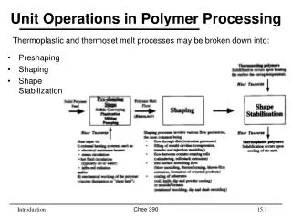
Injection Molding Cycle Injection molding involves two basic steps: • Melt generation by a rotating screw • Forward movement of the screw to fill the mold with melt and to maintain the injected melt under high pressure Injection molding is a “cyclic” process: • Injection: The polymer is injected into the mold cavity. • Hold on time: Once the cavity is filled, a holding pressure is maintained to compensate for material shrinkage. • Cooling: The molding cools and solidifies. • Screw-back: At the same time, the screw retracts and turns, feeding the next shot in towards the front • Mold opening: Once the part is sufficiently cool, the mold opens and the part is ejected • The mold closes and clamps in preparation for another cycle.
* Schematic of thermoplastic Injection molding machine Process & machine schematics
Injection Unit • Purpose: to liquefy the plastic materials and then inject the liquid into mold • Resin is introduced through hopper • Some machines can have several hoppers (to fed filler, colorants, other additives) • However, due to limited size of barrel, mixing capability is poor
Injection Unit • Barrel made of heavy steel cylinder to withstand the pressure and temperature involved in melting the resin • 2 types of system used in injection molding; • Reciprocating screw- similar to extruder screw but with unique reciprocating action • Ram injector:plunger action
Injection Unit • 3 sections • Feed section- to advance the resin • Compression section- to melt the resin • Metering section- to homogenize the resin and pump it forward • The screw of injection molding machine is shorter than extruder, L/D ratios are 12:1 and 20:1 • Low L/D ratios suggest the mixing is less efficient in the injection molding machine
Reciprocating Screw Injection Molding Machine • Advantages • More uniform melting • Improved mixing or additives and dispersion throughout the resin • Lower injection pressure • Fewer stresses in the part • Faster total cycle
Ram Injection- Injection Molding Machine • In this type of injection molding, the resin is fed from a hopper into the barrel, and heated through thermal energy from the heaters • The molten resin is collect in a pool in a barrel celled injection chamber • The molten resin is then push forward by the action of plunger (ram or piston)
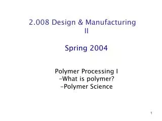
Nozzle Sprue Mold Basics Core Plate Cavity Plate Cavity Runner Gate Melt Delivery Moulding Core Cavity
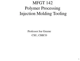
Nozzle Knob Runner Cavity Part Stripper plate Core Injection Molding for a plastic cup
Knob Nozzle Nozzle Runner Cavity Runner Cavity Cavity Part Part Part Stripper plate Complete IM for a plastic cup
Liquid monomers are placed in the mold avoiding the need to use temperature to melt the polymer or pressure to inject it. The monomers polymerize in the mold forming the part. Reaction Injection Molding
Extrusion Extrusion a Greek word: To push out An Extruder is a pump that supplies a continuous stream of material to a shaping tool or post shaping process. Objective One of the most famous and easiest method of plastic processing. Use is not restricted to Plastics, some metals are also extruded (e,g. Al window frames).
Extruder : Mechanical assembly used to melt and push the material Extrusion Line: A typical set up that shows the complete arrangement and sequencing of all the important auxiliaries involved along with extruder to produce any uniform product. Barrel: The upper portion of extruder that covers the screw. Pipes or tubings: The parts which are in hollow cylindrical shape. Profiles: Parts that are hollow but not cylindrical. Die: The shaping tool installed usually at the end of a typical processing equipment.
Advantages and Disadvantages • Uniform products • Continuous Process • High production • Low processing cost • Flexibility of Raw materials • Can act as compounder. • No narrow and complex part • Low extrusion pressures • Uniform products only • Screw is almost material specific
Extrusion Line Figure 10.1
Extrusion • Pellets of the polymer are mixed with coloring and additives. • The material is heated to its proper plasticity. • The material is forced through a die. under pressure resulting in an endless product of constant cross section • The material is cooled.
Blown Film Extrusion • A web under 0.254 mm thickness is called a film (Packaging industry uses 0.10mm) • Materials over these dimensions are called sheets. • Thermoplastics are usually blown into films. • Die is fed from side. • Tubular die is used after extruder • The inflated film is air cooled. • The size is controlled through die gap and size rings around the blown tube, by the internal air pressure and speed of take-off rolls. • Several guide rolls are used to align the blown tube. • A collapsing device is used for to make passage of tube through nip rolls.
The trapped air that forms the continuous tube is directed through mandrel via die. • Once the bubble is formed, the controlled air pressure required to make tube stable is kept constant. • To speed up lines and improve output performances, internal bubble cooling (IBC) systems are extensively used. They direct cool air at low velocity to enter and exit the inside of the bubble.
Drag the extrudate up to the top nip • Pass it through idle rolls to the winder
Adjust the blow up ratio by introducing the air by slowly turning the air valve. • After the desired size is obtained, close the valve
Extrusion Blow Molding • Resembles film blowing in some aspects • Cylindrical extrudate is required so a mandrel is to be used. • Air may be inserted through a pin in the mandrel or through the bottom of the mold into the parison. • Extrusion is a continuous process where as blow molding is a discrete process. • Continuous EBM (Rising Mold System, Parison Transfer System, Rotational Molding) • Intermittent EBM (Reciprocating Screw, Accumulator System)
Compression Molding • Pre-formed blanks, powders or pellets are placed in the bottom section of a heated mold or die. • The other half of the mold is lowered and pressure is applied. • The material softens under heat and pressure, flowing to fill the mold. Excess is squeezed from the mold. If the polymer is a thermoset, cross-linking occurs in the mold. • The mold is opened and the part is removed.
5) De-moulding 3) Squeeze to final dimensions 4) Resin Cure 2) Mould Closure 1) Placement of Charge
Thermoforming • Shaping of materials (sheets and films) by heating until the material softens and then forcing the material to adopt the shape of mold. • The forcing medium includes vacuum, air pressure, or mechanical actions.
Pros & Cons Pros • Low machine cost • Low temp. requirements • Low mold cost • Low pressure requirements • Larger parts can easily be formed • Fast mold cycles Cons • High raw material cost • High scap • Limited part shape • Poor part finish • Inherent wall thickness variation • Common internal stresses
Types of Thermoforming process • Straight vacuum forming • Pressure Forming • Plug-Assist Forming • Reverse Draw Forming • Free Forming • Drape Forming • Snap-back Forming • Matched-Die Forming • Mechanical Forming
Straight Vacuum Forming • Simplest from all others • Straight sheet of thermoplastic is clamped above the mold • Mold has vents connected to vacuum pump • Out side pressure of air forces the sheet to press due to vacuum. • Max. Pressure therefore will be 1 atm. • Very poor control over wall thickness and corners
Pressure Forming • Positive air pressure is used to force the material in heated form. • Same mechanism as that was of straight vacuum forming except the vacuum. • The process can be done at low temperatures and faster cycles. • Good finish than vacuum forming is obtained.
Process Description Material Mould Arm Heat Plate b) Heating the Mould Spray Nozzles/Fan Final Part d) Demoulding c) Cooling • The rotating mould is transferred into an oven, polymer sticking to the walls. • Once the powder consolidates, the mould is cooled, and the part removed. Rotational Molding a) Charging the Mould • A large hollow mould is charged with thermoplastic powder, and rotated.
Products Rotational Molding Wide range of complex hollow products:
Process Description Preheating Heated Die Cooled Die Prepreg Tape or Sheets TP Pultrusion • Prepreg is fed into a preheating section, bringing TP close to Tmelt. • The heated die has a slight taper, gradually shaping to the final cross section. • The product is cooled, taking on the required solid cross section.