Download
1 / 14
140 likes | 227 Views
EFW SOC Utilization INT, Commissioning, Ops. John Bonnell Space Sciences Laboratory University of California, Berkeley. EFW SOC Utilization Outline. EFW SOC Utilization Instrument- and SC-level Integration and Test. Instrument Commissioning: Turn-On and Check Out Boom Deploys

E N D
EFW SOC UtilizationINT, Commissioning, Ops John Bonnell Space Sciences Laboratory University of California, Berkeley
EFW SOC UtilizationOutline EFW SOC Utilization Instrument- and SC-level Integration and Test. Instrument Commissioning: Turn-On and Check Out Boom Deploys Nominal Operations: Conditions for Nominal Operations State-of-Health Monitoring and Trending Commanding and Day-to-Day Operations
EFW SOC UtilizationIntegration and Test EFW integration and test consists of two phases: Instrument-level Integration and Test (including TVAC testing). Spacecraft-level Integration and Test (including TVAC testing, Mission Sims). Instrument-Level INT: Occurs at UCB. Is supported by the CTG, connected to the EFW instrument via the Spacecraft Emulator (SCE). Board-level testing prior to Instrument INT is supported by the CTG, connected to individual sub-systems via the Backplane Interface Board (reviewed at EFW I-CDR, Oct 2009; beyond the scope of this review). Spacecraft-Level INT: Occurs at APL. Is supported by the CTG, connected to the EFW instrument via the Spacecraft and MOC (INT MOC). User-facing interface does not change from Instrument- to SC-Level INT.
EFW SOC UtilizationInstrument Commissioning EFW Commissioning consists of two phases: Initial instrument turn on and check out. Radial and axial boom deploys. May occur at RBSP MOC (using Test SOC; prefered) or at EFW SOC (using Flight SOC). Turn-On and Checkout consists of stowed functional tests (duplicates of SC-level INT procs and data, which are in turn duplicates of Inst-level INT procs and data). Commanding performed via scripts on CTG by EFW Operator. Connection to EFW Instrument is via spacecraft and Flight MOC. User Interface to EFW instrument does not change from INT to Commissioning and Ops.
EFW SOC UtilizationInstrument Commissioning: Boom Deploys Baseline EFW boom deploy plan already developed (RBSP_EFW_TN_003C_EFW_BoomDeploySequence.doc). Boom deploy power controlled by MOC (SC service). Boom deploy commanding through EFW SOC (test or flight). Commanding via scripts of FSW commands, run on the CTG, with feedback on status and progress of deploy via RealTime Engineering telemetry: DEPPAIR: which pair of booms enabled. DEPSTAT A/B: deploy motor status. DELN A/B: number of clicks deployed so far. Deploy commands are of the form: Deploy a pair of booms N clicks. Deploy a single boom N clicks. FSW monitors deploy, and maintains pair-wise deploys within 2 clicks of each other, until deploy is complete, or deploy is aborted. Heritage system (and code!) from Polar, Cluster, THEMIS.
EFW SOC UtilizationInstrument Commissioning: Radial Booms Deploy For radial boom deploys, conservation of angular momentum and known mass properties of SC and booms allow for prediction of spin rate as a function of boom stroke (number of clicks deployed) Spin rate changes during staged, pair-wise boom deploy illustrated below. Spin rate vs. boom stroke and time during deploy used to monitor state of deploy and abort, if required. Baseline 15-day parallel deploy schedule between both observatories incorporated into current Mission Timeline. Fine wire unfurling
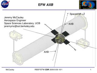
EFW SOC Utilization Instrument Commissioning: Axial Booms Deploy Axial boom deploy occurs after radial boom deploy is complete, and observatory mass properties and dynamics confirmed (typically no significant delay required). Axial booms deployed singly, in stages using motor deploy system to ≈5-m stroke (≈10-m tip-to-tip). Final deploy lengths trimmed in few-cm increments using Survey axial E-field and SC potential estimates to reduce common-mode signal. Trim phase occurs in parallel with other instrument commissioning activities. See the following EFW Technical Note for further analysis and details: RBSP_EFW_TN_023C_AXB_motor_drive_and_measurement_requirement.doc
EFW SOC Utilization Instrument Health and Status Monitoring Instrument State-of-Health (SOH) monitored through near-real-time or playback engineering data via the SOC-CTG, or during SOH generation via service of the PDP CSCI. SOH compared against red/yellow limit database. Off-Nominal conditions leads to: Notification of EFW SOC personnel (page, e-mail). Issuance of scripted commands, for selected well-known off-nominal conditions (example: CRRES DDD-false commanding and resets).
EFW SOC Utilization Normal On-Orbit Operations (1) Commanding Complete instrument state (sensor biasing and data collection) set by ~50 commands. Instrument configuration changes infrequently (~1/few weeks, after initial commissioning phase). ~daily commanding to support ground selection of burst segments as needed: Services provided by BSEL used by EFW Tohban (duty scientist) to select Burst2 intervals for playback (see SOC-PDR AI-20 Response and RBSP-EFW-TN_037B_FlashManagement for details.. Commands generated by CTG in response to request. Commands queued to MOC by SOC personnel (EFW Operator, not Tohban). Typical daily uplink rate of < 600 bytes/day; much less than 125 kbytes/day share of uplink rate (see SOC-PDR AI-18 response for details). ~monthly Sensor Diagnostic Tests (sensor current and voltage bias sweeps) to confirm and optimize instrument biasing.
EFW SOC Utilization Normal On-Orbit Operations (2) Burst Management (RBSP_EFW_SYS_016B_BurstTriggers) Higher-rate waveform data (E, V, and SCM) collected continuously and banked into SDRAM and FLASH in seconds to minutes long segments (many days of B1 storage; many minutes of B2 storage). Each segment tagged with “Burst Quality” computed on-board from DC or AC fields data cues (Filter Bank AC E or B, cues from other instruments). B1 playback is through ground selection based on Survey data and other data sources (geophysical indices, etc.); on-board with Burst Quality allows for autonomous selection and playback, as needed (vacations, illness, ennui, etc.). B2 survival and playback selection on-board is based on Burst Quality; playback selection includes option for forced collection (supports INT, and some possible campaign modes). B1 and B2 support for time-tagged campaign modes available as well (e.g. BARREL support). Inter-Instrument Burst Data EFW message includes axial sensor status (illuminated/eclipsed), sensor sweep status (static/sweeping), and current burst-valuation algorithm ID and value.
EFW SOC Utilization Command Generation EFW-SOC shall generate commands by reference to UTC, as well as MOC data products (predicted ephemerides, etc.) and other data assets (e.g.. Geomagnetic indices). EFW commands shall be validated as needed by running command load on EFW TestBed (ETU) and verifying appropriate change of state, data production, and instrument configuration. Novel instrument commanding and configurations shall be tracked using an Instrument Configuration Change Request (ICCR), as in the THEMIS/ARTEMIS project. Command validation shall occur prior to transmission of command load from EFW-SOC to RBSP-MOC. Verification of current MET↔UTC SCLK Kernel shall occur prior to translation of EFW commands from UTC to MET. Command receipt will be verified after transmission using standard MOC data products.
EFW SOC UtilizationProgress Since I-PDR and M-PDR Provided measurements of SPB boom cable damping parameters in support of Project GNC boom dynamics modeling efforts (Q3-Q4 2008): Boom settling to < 0.5-deg within 8-12 hours post-repointing. Worked with Project GNC and L&EO Planning to flesh out AXB deploy and length trim plan. Data collection in support of trim occurs in parallel with subsequent instrument commissioning activities. Worked with Project L&EO Planning to detail EFW Commissioning timeline activites: Instrument Turn-On SPB Deploys AXB Deploys and Length Trims Developed ALT-MAG data product and delivery path to support contingency collection of EMFISIS-MAG data for science and Ops (GNC) support if EMFISIS-MEB is non-operational.

![isort :: [Int] -> [Int]](https://cdn2.slideserve.com/4488600/slide1-dt.jpg)
![class Stack { int data[]; int first; int max; Stack(int dimensione) {](https://cdn3.slideserve.com/6370396/slide1-dt.jpg)