Download
1 / 70
760 likes | 1.17k Views
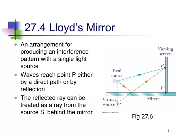
27.4 Lloyd’s Mirror. An arrangement for producing an interference pattern with a single light source Waves reach point P either by a direct path or by reflection The reflected ray can be treated as a ray from the source S’ behind the mirror. Fig 27.6.

E N D
27.4 Lloyd’s Mirror • An arrangement for producing an interference pattern with a single light source • Waves reach point P either by a direct path or by reflection • The reflected ray can be treated as a ray from the source S’ behind the mirror Fig 27.6
Interference Pattern from the Lloyd’s Mirror • This arrangement can be thought of as a double slit source with the distance between points S and S’ comparable to length d • An interference pattern is formed • The positions of the dark and bright fringes are reversed relative to pattern of two real sources • This is because there is a 180° phase change produced by the reflection
Phase Changes Due To Reflection • An electromagnetic wave undergoes a phase change of 180° upon reflection from a medium of higher index of refraction than the one in which it was traveling • Analogous to a pulse on a string reflected from a rigid support Fig 27.7
Phase Changes Due To Reflection, cont • There is no phase change when the wave is reflected from a boundary leading to a medium of lower index of refraction • Analogous to a pulse in a string reflecting from a free support Fig 27.7
27.5 Interference in Thin Films • Interference effects are commonly observed in thin films • Examples include soap bubbles and oil on water • The varied colors observed when white light is incident on such films result from the interference of waves reflected from the opposite surfaces of the film
Interference in Thin Films, 2 • Facts to keep in mind • An electromagnetic wave traveling from a medium of index of refraction n1 toward a medium of index of refraction n2 undergoes a 180° phase change on reflection when n2 > n1 • There is no phase change in the reflected wave if n2 < n1 • The wavelength of light λn in a medium with index of refraction n is λn = λ/n where λ is the wavelength of light in vacuum
Interference in Thin Films, 3 • Assume the light rays are traveling in air nearly normal to the two surfaces of the film • Ray 1 undergoes a phase change of 180° with respect to the incident ray • Ray 2, which is reflected from the lower surface, undergoes no phase change with respect to the incident wave Fig 27.8
Interference in Thin Films, 4 • Ray 2 also travels an additional distance of 2t before the waves recombine • For constructive interference • 2 n t = (m + ½ ) λ m = 0, 1, 2 … • This takes into account both the difference in optical path length for the two rays and the 180° phase change • For destructive interference • 2 n t = m λ m = 0, 1, 2 …
Interference in Thin Films, 5 • Two factors influence interference • Possible phase reversals on reflection • Differences in travel distance • The conditions are valid if the medium above the top surface is the same as the medium below the bottom surface • If there are different media, these conditions are valid as long as the index of refraction for both is less than n
Interference in Thin Films, 6 • If the thin film is between two different media, one of lower index than the film and one of higher index, the conditions for constructive and destructive interference are reversed • With different materials on either side of the film, you may have a situation in which there is a 180o phase change at both surfaces or at neither surface • Be sure to check both the path length and the phase change
27.6 Diffraction • Diffraction occurs when waves pass through small openings, around obstacles, or by sharp edges • Diffraction refers to the general behavior of waves spreading out as they pass through a slit • A diffraction pattern is really the result of interference
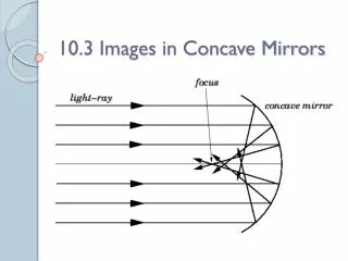
Diffraction Pattern • A single slit placed between a distant light source and a screen produces a diffraction pattern • It will have a broad, intense central band • Called the central maximum • The central band will be flanked by a series of narrower, less intense secondary bands • Called side maxima • The central band will also be flanked by a series of dark bands • Called minima
Diffraction Pattern, Single Slit • The central maximum and the series of side maxima and minima are seen • The pattern is, in reality, an interference pattern Fig 27.12
Diffraction Pattern, Penny • The shadow of a penny displays bright and dark rings of a diffraction pattern • The bright center spot is called the Arago bright spot • Named for its discoverer, Dominque Arago Fig 27.13
Diffraction Pattern, Penny, cont • The Arago bright spot is explained by the wave theory of light • Waves that diffract on the edges of the penny all travel the same distance to the center • The center is a point of constructive interference and therefore a bright spot • Geometric optics does not predict the presence of the bright spot • The penny should screen the center of the pattern
Fraunhofer Diffraction Pattern • Fraunhofer Diffraction Pattern occurs when the rays leave the diffracting object in parallel directions • Screen very far from the slit • Could be accomplished by a converging lens Fig 27.14
Fraunhofer Diffraction Pattern – Photo • A bright fringe is seen along the axis (θ = 0) • Alternating bright and dark fringes are seen on each side Fig 27.14
Single Slit Diffraction • The finite width of slits is the basis for understanding Fraunhofer diffraction • According to Huygen’s principle, each portion of the slit acts as a source of light waves • Therefore, light from one portion of the slit can interfere with light from another portion
Single Slit Diffraction, 2 • The resultant light intensity on a viewing screen depends on the direction q • The diffraction pattern is actually an interference pattern • The different sources of light are different portions of the single slit
Single Slit Diffraction, Analysis • All the waves that originate at the slit are in phase • Wave 1 travels farther than wave 3 by an amount equal to the path difference • (a/2) sin θ • If this path difference is exactly half of a wavelength, the two waves cancel each other and destructive interference results • In general, destructive interference occurs for a single slit of width a when sin θdark = mλ / a • m = ±1, ±2, ±3, …
Single Slit Diffraction, Intensity • The general features of the intensity distribution are shown • A broad central bright fringe is flanked by much weaker bright fringes alternating with dark fringes • Each bright fringe peak lies approximately halfway between the dark fringes • The central bright maximum is twice as wide as the secondary maxima Fig 27.15
Resolution • The ability of optical systems to distinguish between closely spaced objects is limited because of the wave nature of light • If two sources are far enough apart to keep their central maxima from overlapping, their images can be distinguished • The images are said to be resolved • If the two sources are close together, the two central maxima overlap and the images are not resolved
27.7 Resolved Images, Example • The images are far enough apart to keep their central maxima from overlapping • The angle subtended by the sources at the slit is large enough for the diffraction patterns to be distinguishable • The images are resolved Fig 27.17
Images Not Resolved, Example • The sources are so close together that their central maxima do overlap • The angle subtended by the sources is so small that their diffraction patterns overlap • The images are not resolved Fig 27.17
Resolution, Rayleigh’s Criterion • When the central maximum of one image falls on the first minimum of another image, the images are said to be just resolved • This limiting condition of resolution is called Rayleigh’s criterion
Resolution, Rayleigh’s Criterion, Equation • The angle of separation, qmin, is the angle subtended by the sources for which the images are just resolved • Since l << a in most situations, sin q is very small and sin q» q • Therefore, the limiting angle (in rad) of resolution for a slit of width a is • To be resolved, the angle subtended by the two sources must be greater than qmin
Circular Apertures • The diffraction pattern of a circular aperture consists of a central bright disk surrounded by progressively fainter bright and dark rings • The limiting angle of resolution of the circular aperture is • D is the diameter of the aperture
Circular Apertures, Well Resolved • The sources are far apart • The images are well resolved • The solid curves are the individual diffraction patterns • The dashed lines are the resultant pattern Fig 27.18
Circular Apertures, Just Resolved • The sources are separated by an angle that satisfies Rayleigh’s criterion • The images are just resolved • The solid curves are the individual diffraction patterns • The dashed lines are the resultant pattern Fig 27.18
Circular Apertures, Not Resolved • The sources are close together • The images are unresolved • The solid curves are the individual diffraction patterns • The dashed lines are the resultant pattern Fig 27.18
Resolution, Example Fig 27.19 • Pluto and its moon, Charon • Left – Earth based telescope is blurred • Right – Hubble Space Telescope clearly resolves the two objects
27.8 Diffraction Grating • The diffracting grating consists of a large number of equally spaced parallel slits • A typical grating contains several thousand lines per centimeter • The intensity of the pattern on the screen is the result of the combined effects of interference and diffraction • Each slit produces diffraction, and the diffracted beams interfere with one another to form the final pattern
Diffraction Grating, Types • A transmission grating can be made by cutting parallel grooves on a glass plate • The spaces between the grooves are transparent to the light and so act as separate slits • A reflection grating can be made by cutting parallel grooves on the surface of a reflective material
Diffraction Grating, cont • The condition for maxima is • d sin θbright = m λ • m = 0, 1, 2, … • The integer m is the order number of the diffraction pattern • If the incident radiation contains several wavelengths, each wavelength deviates through a specific angle Fig 27.20
Diffraction Grating, Intensity • All the wavelengths are seen at m = 0 • This is called the zeroth order maximum • The first order maximum corresponds to m = 1 • Note the sharpness of the principle maxima and the broad range of the dark areas Fig 27.21