Download
1 / 10
100 likes | 102 Views
Empty. Automatic sample loop centering at SSRL Timothy McPhillips. Click-to-center interface in Blu-Ice. Clicking on video image moves clicked point to center of view. System is calibrated by staff using automated procedure. Camera is calibrated across the full zoom range.

E N D
Empty Automatic sample loop centering at SSRLTimothy McPhillips
Click-to-center interface in Blu-Ice • Clicking on video image moves clicked point to center of view. • System is calibrated by staff using automated procedure. • Camera is calibrated across the full zoom range.
Hardware specifications and limitations • Camera with motorized zoom and frame grabber • Camera view is normal to beam and to phi axis. • 1 pixel = 19 µm at min. zoom. • 1 pixel = 1.9 µm at max. zoom. • Kappa goniometer • Phi axis speed = 28º/sec. • Acceleration time = 50 ms. • Kappa must be zero during centering operations. • Motorized sample stage • Sample x, y, and z axes rotate with phi. • Speed = 570 µm/sec. • Acceleration time = 100 ms. Goniometer Phi axis Cryo-stream Samplecamera
Automatic centering procedure • Center loop tip at minimum zoom, then at maximum zoom. • Acquire 18 images of sample, rotating phi 10º between each image. • Determine 3-D bounding box for sample plus loop. • Center bounding box with largest face towards camera. Note that the system centers the loop plus the crystal.
Determination of the 3D bounding box • Determine which of the 18 images corresponds to the face-on and edge-on views of the sample. • Use differences between the face-on and edge-on images to distinguish between the loop and the loop stem. • Measure the 3-D bounding box parameters from the face-on and edge-on images.
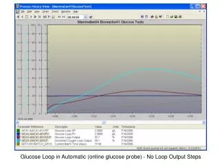
Finding face-on and edge-on views • Height of a 2-D bounding box is determined for each of the 18 views of the sample. • Plot of bounding box height vs angle typically yields a smooth curve with minimum and maximum 90º apart. • Image at maximum is taken as the face-on view, image at minimum is the edge-on view.
Distinguishing loop from stem • Scan across the image of the face-on view of the sample, calculating the distance between the uppermost and lowermost pixel occupied by the loop in each column of the image. • Repeat for the edge-on view. • Find the difference between the distances in the two images for each column. • Classify the columns as loop or loop stem based on the magnitude of the differences
Distinguishing loop from stem Subtract
Software implementation Operations provided by hardware server: • A camera DHS provides operations for acquiring and analyzing images of the sample. • get_loop_tip returns image coordinates of extreme tip of sample. • add_image_to_list saves current image to an indexed list in memory. • find_bounding_box analyzes list of images and finds a 3-D bounding box for the loop. Operation implemented as a Tcl script: • The center_loop scripted operation contains the logic for centering a sample loop automatically. • Starts and waits for operations provided by the camera DHS. • Moves goniometer and sample motors as needed to center loop. Blu-Ice Center loop DCSS center_loop Image operations Motor moves Camera DHS Motor DHS Axis 2400 Galil 2180 Sample camera
Answers to common questions • The center of the loop is placed near the center of the goniometer in ~99% of cases. Damage to samples occur only when there is a hardware failure. • The procedure takes about 40 seconds to complete. • Optimal results are obtained when the loop size closely matches the crystal size and excessive solvent is avoided. • The user may quickly refine the centering using the click-to-center interface. • The system centers the aggregate of the crystal plus the loop. • The beam size is not adjusted based on the 3-D bounding box dimensions. • The loop will typically end up within ~10° of one of the two face-on views each time it is mounted and centered. • Different approaches to loop centering are likely to give different results. • Saving of crystal position for later use is not supported. • Appropriate lighting is critical for reliable centering. The SSRL Structural Molecular Biology program is funded by DOE BER, NIH NCRR, and NIH NIGMS. The Collaboratory forMacromolecular Crystallography is supported by the NIH, NCRR as a supplement to the SSRL Synchrotron Radiation Structural Biology Resource (P41-RR-01209).