Download
1 / 21
220 likes | 307 Views
Reverse Engineering and Machining of 3D Face Using MasterCAM. Abdolreza Bayesteh Kaustubh Ladia. August 02, 2012. Geometry Acquisition . Step 1

E N D
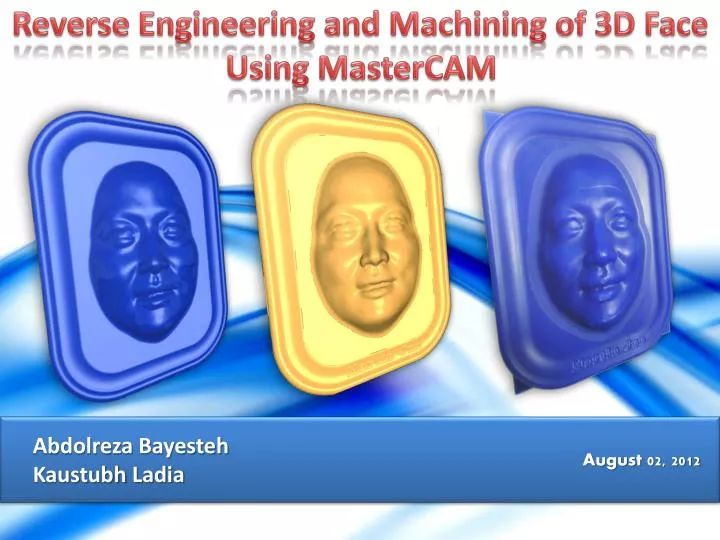
Reverse Engineering and Machining of 3D Face Using MasterCAM AbdolrezaBayesteh KaustubhLadia August 02, 2012
Geometry Acquisition Step 1 The 3D scanner directs a series of reference patterns onto an object. The light deflects onto the object’s surface. The scanner captures these images to calculate the object’s depth and surface information. Step 2 The 3D scanner’s triangulation engine processes the images to acquire the data needed to create a 3D model. Automated 3D capture drastically reduces the time and cost in capturing complex physical measurements. 1 2 3 4 5 6 7 8 9 10 11 12 13 14 15 16 17 18 19
Modeling Import Scanned Data Remove geometrical errors Achieve desired area 1 2 3 4 5 6 7 8 9 10 11 12 13 14 15 16 17 18 19
Mesh Optimization Initially the no. of triangles in the part was too high, so it was difficult to manipulate the part, so mesh optimisation had to be performed to reduce the no. of triangles. 1 2 3 4 5 6 7 8 9 10 11 12 13 14 15 16 17 18 19
Mesh Smoothing 1 2 3 4 5 6 7 8 9 10 11 12 13 14 15 16 17 18 19
Surface generation STL file converted to STEP file format in CATIA. 1 2 3 4 5 6 7 8 9 10 11 12 13 14 15 16 17 18 19
Final Design 1 2 3 4 5 6 7 8 9 10 11 12 13 14 15 16 17 18 19
Toolpath Generation in Mastercam • For the final machining of the part Core Roughing, Rest Roughing, Horizontal Area Finishing, Scallop Finishing, Surface High Speed Pencil Finishing, Contour 3D and Contour 2D toolpaths were used. • Stock Size: 160 X 125 X 76 mm. • Tools Used: • Tool 1:Tool 1 was used for the Core Roughing and Contour 2D operation as roughing operation should be performed with the tool having the least rake angle to remove the maximum amount of material. • Tool 2:Tool 2 was used for the Scallop finishing (Lower Face), Scallop Finishing (Frame) toolpaths. Tool 5 couldn’t be used for these operations as the overall height for the tool was small and as a result the tool would clash with the workpiece. • Tool 4:Tool 4 was used for the Rest Roughing and Horizontal Area Finishing toolpaths. For the Horizontal Area Finishing toolpath, the tool had to machine the flat area between the face and the frame which had a gap of 7 mm, so tools 1, 2 couldn’t be used here as they had larger diameters. • Tool 6:Tool 6 was used for Scallop Finishing (Upper Face), Pencil Finishing and Contour 3D toolpaths • For the finishing operations, Stock to leave on walls: 0 mm, Stock to leave on Floor: 0 mm. 1 2 3 4 5 6 7 8 9 10 11 12 13 14 15 16 17 18 19
CAM Operation #1 Strategy : Core Roughing Tool : T1 Stepdown: 3.0 mm Total Tolerance: 0.5 mm Machining Time : 27 min 1 2 3 4 5 6 7 8 9 10 11 12 13 14 15 16 17 18 19
CAM Operation #2 Strategy :Rest Roughing Rest Roughing was used to machine the stock left over from the previous roughing operation to remove additional stock material prior to finishing toolpaths. Tool : T4 Stepdown:2.0 Total Tolerance: 0.5 mm Machining Time : 7 min 1 2 3 4 5 6 7 8 9 10 11 12 13 14 15 16 17 18 19
CAM Operation #3 Strategy : Horizontal area finishing Horizontal area finishing is used to machine the flat area on the model i.e. the area between the face and the frame. Tool : T4 Machining Time : 2 min 1 2 3 4 5 6 7 8 9 10 11 12 13 14 15 16 17 18 19
CAM Operation #4 Strategy : Scallop Scallop finishing toolpath is used to stepover along the 3D shape at a constant stepovervalue. Tool :T6 Stepover: 0.3 (For better surface Quality) Machining Time : 17 min Total tolerance: 0.02 mm 1 2 3 4 5 6 7 8 9 10 11 12 13 14 15 16 17 18 19
CAM Operation #5 Strategy : Scallop Stepover: 0.5 Tool : T2 Total tolerance: 0.02 mm Machining Time : 15 min Tool Containment Compensate to outside was selected for this toolpath. This was done to remove the boundary between the upper and lower face toolpaths. 1 2 3 4 5 6 7 8 9 10 11 12 13 14 15 16 17 18 19
CAM Operation #6 Strategy : Scallop Tool : T2 Stepover: 0.4 Machining Time : 27 min 1 2 3 4 5 6 7 8 9 10 11 12 13 14 15 16 17 18 19
CAM Operation #7 Strategy : Contour 3D Contour 3D was used for engraving the name onto the frame. Tool : T6 Depth(Final lowest machining depth): -0.15 Machining Time : 1 min 1 2 3 4 5 6 7 8 9 10 11 12 13 14 15 16 17 18 19
CAM Operation #8 Strategy : Contour 2D This last toolpath was used to machine the excess material from the outermost frame surface. Tool : T1 Depth Cut: Max Rough Step: 3.0, Finish Step: 1.0. Machining Time : 3 min Total Machining time: 110 min 1 2 3 4 5 6 7 8 9 10 11 12 13 14 15 16 17 18 19
Strategy comparison 1 3 4 2 5 6 1 2 3 4 5 6 7 8 9 10 11 12 13 14 15 16 17 18 19
Technical Challenges, Solutions • After obtaining the NC program code for all the selected toolpaths, the workpiece was machined in the HAAS 3 Axis CNC machine. The workpiece material was MachinableWax. • While Core Roughing operation was being performed on the workpiece, some material cracked and some chunks of material broke off the workpiece. This was due to: • The melting of the wax material was due to high temperature and cutting forces of machining. • The workpiece was clamped in the fixture with too much force which led to cracks developing on the workpiece. • This resulted in a slight defect in the final machined part. This problem can be avoided by using a material with a higher strength like Aluminum, HDPE. • To prevent this from happening again during the subsequent machining operations, the spindle speed was reduced by 40 % to 1800 rpm and the feed rate was increased by 20 % for all the machining operations. • But still, a boundary can be seen in the final machined part. This was due to the tool height compensation not being set correctly for the two different tools used here. 1 2 3 4 5 6 7 8 9 10 11 12 13 14 15 16 17 18 19
Final Machined Part in a 3 Axis CNC Machine 1 2 3 4 5 6 7 8 9 10 11 12 13 14 15 16 17 18 19
Project Procedure http://www.youtube.com/watch?v=jkas3W1E_dI 1 2 3 4 5 6 7 8 9 10 11 12 13 14 15 16 17 18 19