Download
1 / 61
620 likes | 838 Views
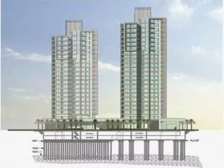
Graduation Project 3D Dynamic and Soil Structure Interaction Design for Al-Huda Building . This project is formed of six basic chapters :- Chapter 1: Introduction, that describes the structure location, loads, materials, codes and standards and the basic structural system of the structure.

E N D
Graduation Project3D Dynamic and Soil Structure Interaction Design for Al-Huda Building
This project is formed of six basic chapters:- Chapter 1: Introduction, that describes the structure location, loads, materials, codes and standards and the basic structural system of the structure. Chapter 2: Preliminary design, which introduces the selection of slab, beams and columns dimensions according to ACI code. Chapter 3: Structural verification, which introduces checks for the structure as one story to compatibility, equilibrium and stress strain relationship then replicate the structure to seven stories and the same checks well be done. • Chapter 4: Static design, which introduces design of different structural elements using SAP program which are slab, beams, columns, footings and tie beams. Chapter 5: Dynamic analysis, which introduces analysis of the building using manual solution and SAP program. Chapter 6: Soil -structure interaction, here we compare the results of different soil cases in static and dynamic conditions on the building.
Chapter One Introduction
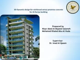
1.1 Description of Project -Type of building: Office Building -Area of the building (865 m2) -Number of stories ( 7 stories ) -Ground floor contains Garages and Stories with elevation (4.5 m) -Remaining floors contain offices with elevation (3.75 m)
1.2LocationThe site of the building is located in Ramallah on a rocky soil with bearing capacity(3.5kg/cm 2) 1.3 Analysis philosophy We will represent the results of the design and analysis of the building through various methods of analysis in order to reach the best. Comparisons between different results, first static then dynamic analysis will be done. 1.4Program analysis (SAP2000 v.14.2)
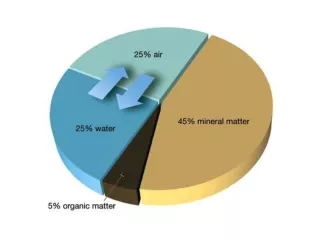
1.5 CODE (ACI318M-08) 1.6 Material 𝒇'c=250kg/cm2 ℱy=4200kg/cm2 1.7 Loads Ultimate load =1.2 (DL+SID) +1.6 LL DL: dead load SID: super imposed load (0.3 ton/m2) LL: live load (0.4 ton/m2)
Chapter Two Preliminary Design
-Beams dimension: h=L /18.5=900/18.5=50 cm use 50 x 60 cm-Columns dimension: use 70x70 cm-Slab thickness: use t= 20 cm
Check slab thickness-Calculate α for all beams:-α:ratio of beam stiffness to slab stiffness
The average ratio αm for panels 1,2,3,4αm for panels 1= =3.9αm for panels 2=3.3αm for panels 3=3.5 αm for panels 4=2.9since αm >2.0 apply equation 9.13ACI codeso; select thickness of slab is 20 cm.
Check column dimension -critical column is B-2 Tributary area = 56.125 m2
Pu= 7246.5 KN Pcolumn=ϕ (0.8) [ 0.85 f/c( Ag- As ) + fy As]7246.5x100=0.65x0.8[ 0.85x250 ( Ag- 0.02Ag ) + 4200x 0.02Ag]Ag=4768.4 cm2 69x69 cm 70x70 cm OK
Chapter Three Structural Analysis Laws and its verification
3-1 For one storey 3-1.1Compatibility: Compatibility is ok……………….
3-1.2Equilibrium: Dead load (manual) = 965.08 ton. Live load (manual) = 325.62 ton. Super imposed(manual)=244.215 ton.
% of error ( Dead Load ) % of error ( Live Load ) % of error ( Super Imposed Load ) …………….Equilibrium is ok
3-1.3Stress-strain relationship:-Direct design method is applicable . M –ve = 0.65 Mo = 44.74 ton.m M +ve = 0.35 Mo = 24.1 ton.m M -ve (beam)=(0.825)(0.85)(44.74) = 31.37 ton.m M +ve (beam)=(0.825)(0.85)(24.1) = 16.9 ton.m
Results from SAP Moment on the interior negative beam in X-direction Moment on the interior positive beam in X-direction < 10% ok
3-2 For seven stories 3-2.1Compatibility: Compatibility is ok……………….
3-2.2Equilibrium: Dead load (manual) = 5390.83 ton. Live load (manual) = 2279.34 ton. Super imposed(manual)=1709.51 ton.
% of error ( Dead Load ) % of error ( Live Load ) % of error ( Super Imposed Load ) …………….Equilibrium is ok
3-2.3Stress-strain relationship:-Direct design method is applicable . M –ve = 0.65 Mo = 44.74 ton.m M +ve = 0.35 Mo = 24.1 ton.m M -ve (beam)=(0.825)(0.85)(44.74) = 31.37 ton.m M +ve (beam)=(0.825)(0.85)(24.1) = 16.9 ton.m
Results from SAP Moment on the interior negative beam in X-direction Moment on the interior positive beam in X-direction
Chapter Four Static Design of the Building
4.1-Design of slab:- 4-1.1Manual design In this section we take frame 5-5 in the first storey in X-direction moment on column strip for interior span (ton.m) M-ve =5.54 ton.mAs= 2.6cm² (Use 3 Φ12mm\m) M+ve =2.98 ton.mAs= 1.14cm² (Use 2 Φ12mm\m)
moment on middle strip for interior span (ton.m) M-ve =7.83 ton.mAs= 7.48cm² (Use 7 Φ12mm\m) M+ve =4.22 ton.mAs= 4cm² (Use 4 Φ12mm\m)
SAP results : SAP result in X-direction : Note: M1 = M4 M2 = M3 M5 = M7
SAP result in Y-direction : Note : M1= M6 M2 = M5 M3 = M4 M7 = M11 M8 = M10
4.2-Design of beams :- SAP results in X-direction
4.3.2- SAP results for seven storey:- Frame 1-1&6-6 (cm2)
Summary: • From previous figures area of steel for all column in the building which names C1 equal 49cm2 except:- • In the first storey • C.B-2, C.B-5, C.C-2, C.C-5 refers to C3 = 125cm2. • C.B-3, C.B-4, C.C-3, C.C4 refers to C2 = 54cm2 . • In the second storey • C.B-2, C.B-5, C.C-2, C.C-5 refers to C5 = 69cm2 use 14Ø25 • In the last storey • C.D-2, C.D-5 refers to C6 = 58cm2 use 12Ø25
Service load on footing from SAP • summary footing dimension and flexural design:
4.5-Design of tie beams :- • Dimension of tie beam : 40 * 80 cm ρ min = 0.0033 As = ρ * b * d = 0.0033* 40 * 74 = 9.8 cm2 Results from sap :
Chapter Five Dynamic design of the building
5.1-Dynamic analysis 5.1-A SAP and manual results
5.2-Dynamic Design 5.2-A Response spectrum method: Input data : • Ss: mapped spectral acceleration for short periods (0.5) • S1: mapped spectral acceleration for 1.0 sec. periods (0.2) • site class ( C ) • Important factor I=1.25 (refer to IBC2006) • Response modification coefficient R= 3 (refer to IBC2006) • Scale factor = g*I/R = 4.0875