Download

1 / 16
190 likes | 413 Views
Combustion in CI Engine. In a CI engine the fuel is sprayed directly into the cylinder and the fuel-air mixture ignites spontaneously. These photos are taken in a RCM under CI engine conditions with swirl air flow. 1 cm. 0.4 ms after ignition. 3.2 ms after ignition.

E N D
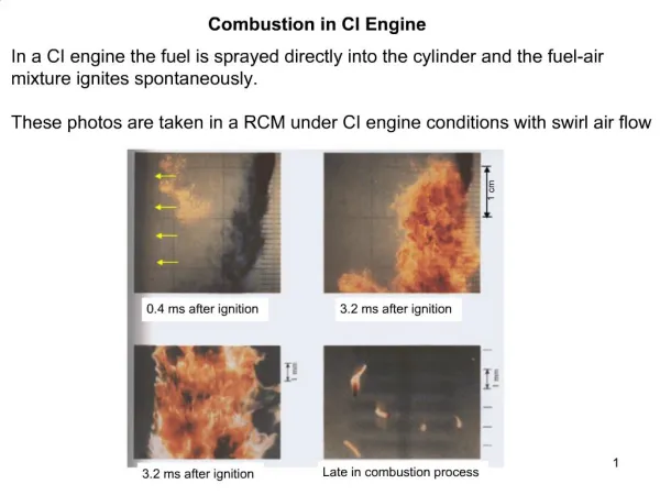
Combustion in CI Engine In a CI engine the fuel is sprayed directly into the cylinder and the fuel-air mixture ignites spontaneously. These photos are taken in a RCM under CI engine conditions with swirl air flow 1 cm 0.4 ms after ignition 3.2 ms after ignition Late in combustion process 3.2 ms after ignition
In Cylinder Measurements This graph shows the fuel injection flow rate, net heat release rate and cylinder pressure for a direct injection CI engine. Start of injection Start of combustion End of injection
Combustion in CI Engine The combustion process proceeds by the following stages: Ignition delay (ab) - fuel is injected directly into the cylinder towards the end of the compression stroke. The liquid fuel atomizes into small drops and penetrates into the combustion chamber. The fuel vaporizes and mixes with the high-temperature high-pressure air. Premixed combustion phase (bc)– combustion of the fuel which has mixed with the air to within the flammability limits (air at high-temperature and high- pressure) during the ignition delay period occurs rapidly in a few crank angles. Mixing controlled combustion phase (cd)– after premixed gas consumed, the burning rate is controlled by the rate at which mixture becomes available for burning. The rate of burning is controlled in this phase primarily by the fuel-air mixing process. Late combustion phase (de)– heat release may proceed at a lower rate well into the expansion stroke (no additional fuel injected during this phase). Combustion of any unburned liquid fuel and soot is responsible for this.
Four Stages of Combustion in CI Engines Start of injection End of injecction 10 30 -20 -10 TC 20
CI Engine Types • Two basic categories of CI engines: • Direct-injection – have a single open combustion chamber into which fuel • is injected directly • Indirect-injection – chamber is divided into two regions and the fuel is • injected into the “prechamber” which is connected to the main chamber via a • nozzle, or one or more orifices. • For very-large engines (stationary power generation) which operate at low • engine speeds the time available for mixing is long so a direct injection • quiescent chamber type is used (open or shallow bowl in piston). • As engine size decreases and engine speed increases, increasing amounts • of swirl are used to achieve fuel-air mixing (deep bowl in piston) • For small high-speed engines used in automobiles chamber swirl is not • sufficient, indirect injection is used where high swirl or turbulence is generated • in the pre-chamber during compression and products/fuel blowdown and mix • with main chamber air.
Ignition Delay Ignition delay is defined as the time (or crank angle interval) from when the fuel injection starts to the onset of combustion. Both physical and chemical processes must take place before a significant fraction of the chemical energy of the injected liquid is released. Physical processes are fuel spray atomization, evaporation and mixing of fuel vapour with cylinder air. Good atomization requires high fuel-injection pressure, small injector hole diam., optimum fuel viscosity, high cylinder pressure (large divergence angle). Rate of vaporization of the fuel droplets depends on droplet diameter, velocity, fuel volatility, pressure and temperature of the air. Chemical processes similar to that described for autoignition phenomenon in premixed fuel-air, only more complex since heterogeneous reactions (reactions occurring on the liquid fuel drop surface) also occur.
Fuel Ignition Quality The ignition characteristics of the fuel affect the ignition delay. The ignition quality of a fuel is defined by its cetane number CN. For low cetane fuels the ignition delay is long and most of the fuel is injected before autoignition and rapidly burns, under extreme cases this produces an audible knocking sound referred to as “diesel knock”. For high cetane fuels the ignition delay is short and very little fuel is injected before autoignition, the heat release rate is controlled by the rate of fuel injection and fuel-air mixing – smoother engine operation.
Cetane Number The method used to determine the ignition quality in terms of CN is analogous to that used for determining the antiknock quality using the ON. The cetane number scale is defined by blends of two pure hydrocarbon reference fuels. By definition, isocetane (heptamethylnonane, HMN) has a cetane number of 15 and cetane (n-hexadecane, C16H34) has a value of 100. In the original procedures a-methylnaphtalene (C11H10) with a cetane number of zero represented the bottom of the scale. This has since been replaced by HMN which is a more stable compound. The higher the CN the better the ignition quality, i.e., shorter ignition delay. The cetane number is given by: CN = (% hexadecane) + 0.15 (% HMN)
Factors Affecting Ignition Delay Injection timing – At normal engine conditions the minimum delay occurs with the start of injection at about 10-15 BTC. The increase in the delay time with earlier or later injection timing occurs because of the air temperature and pressure during the delay period. Injection quantity – For a CI engine the air is not throttled so the load is varied by changing the amount of fuel injected. Increasing the load (bmep) increases the residual gas and wall temperature which results in a higher charge temperature at injection which translates to a decrease in the ignition delay. Intake air temperature and pressure – an increase in ether will result in a decrease in the ignition delay, an increase in the compression ratio has the same effect.
Flame Development Flame development angleDqd – crank angle interval during which flame kernal develops after spark ignition. Rapid burning angleDqb – crank angle required to burn most of mixture Overall burning angle - sum of flame development and rapid burning angles Mass fraction burned
Spark Timing Spark timing relative to TC affects the pressure development and thus the imep and power of the engine. Want to ignite the gas before TC so as to center the combustion around TC. The overall burning angle is typically between 40 to 60o, depending on engine speed. Engine at WOT, constant engine speed and A/F motored
Abnormal Combustion in SI Engine Knock is the term used to describe a pinging noise emitted from a SI engine undergoing abnormal combustion. The noise is generated by shock waves produced in the cylinder when unburned gas ahead of the flame auto-ignites.
Knock As the flame propagates away from the spark plug the pressure and temperature of the unburned gas increases. Under certain conditions the end-gas can autoignite and burn very rapidly producing a shock wave flame shock P,T P,T end-gas time time The end-gas autoignites after a certain induction time which is dictated by the chemical kinetics of the fuel-air mixture. If the flame burns all the fresh gas before autoignition in the end-gas can occur then knock is avoided. Therefore knock is a potential problem when the burn time is long!
Parameters Influencing Knock i) Compression ratio – at high compression ratios, even before spark ignition, the fuel-air mixture is compressed to a high pressure and temperature which promotes autoignition ii) Engine speed – At low engine speeds the flame velocity is slow and thus the burn time is long, this results in more time for autoignition However at high engine speeds there is less heat loss so the unburned gas temperature is higher which promotes autoignition These are competing effects, some engines show an increase in propensity to knock at high speeds while others don’t. iii) Spark timing – maximum compression from the piston advance occurs at TC, increasing the spark advance makes the end of combustion crank angle approach TC and thus get higher pressure and temperature in the unburned gas just before burnout.
Fuel Knock Scale To provide a standard measure of a fuel’s ability to resist knock, a scale has been devised in which fuels are assigned an octane number ON. The octane number determines whether or not a fuel will knock in a given engine under given operating conditions. By definition, normal heptane (n-C7H16) has an octane value of zero and isooctane (C8H18) has a value of 100. The higher the octane number, the higher the resistance to knock. Blends of these two hydrocarbons define the knock resistance of intermediate octane numbers: e.g., a blend of 10% n-heptane and 90% isooctane has an octane number of 90. A fuel’s octane number is determined by measuring what blend of these two hydrocarbons matches the test fuel’s knock resistance.
Octane Number Measurement Note the motor octane number is always higher because it uses more severe operating conditions: higher inlet temperature and more spark advance. The automobile manufacturer will specify the minimum fuel ON that will resist knock throughout the engine’s operating speed and load range.