Download
1 / 60

E N D
ECEN5553 Telecom SystemsWeek #4Readings:[5] "Tech Titans Building Boom"[6a] "A Cloud You Can Trust"[6b] "Security Challenges for the Public Cloud" [7a] "A Fairer Faster Internet" [7b] "The End of IPv4 is Nearly Here- Really"Exam #1 Lecture 17, 27 September (Local) No later than 3 October (Remote DL)Outline Lecture 22, 9 October (Local) No later than 16 October (Remote)
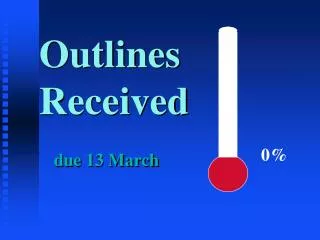
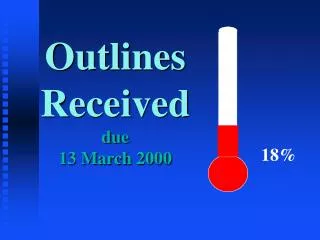
OutlinesReceiveddue 9 October (Local)By 16 October (Remote) 25 %
Ethernet (Shared) Hub • Operates at OSI Level 1 • ‘Electric Cable’Traffic arriving at an input is immediately copied to all other ports on a bit-by bit basis. • Used on LAN's. Pretty much obsolete. • Repeater = single input & single output hub • Not used much on Ethernet any more • Generally now only used on WAN long haul • May be different protocol than Ethernet
Black Box Performance... From Node A To Node A OSI Level 1 LAN Hub Node B Node B Node C Node C Two packets simultaneously show up at input...
Black Box Performance... From Node A To Node A OSI Level 1 LAN Hub Node B Node B Node C Node C ... will overwrite each other, i.e. garbage out. a.k.a. Shared Hub
Black Box Performance... OSI Level 1-2 (Switch) or 1-3 (Router) Two packets simultaneously show up at input...
Black Box Performance... OSI Level 1-2 (Switch) or 1-3 (Router) ... one will be transmitted (when allowed by MAC), the other momentarily buffered...
Black Box Performance... OSI Level 2/3 Switch or Router ... and then transmitted.
10BaseT & Shared Hub PC 53 m PC 8 m Hub PC PC 26 m 17 m One big collision domain.
10BaseT & Half Duplex Switch PC 53 m PC 8 m Switch PC PC 26 m 17 m Four smaller collision domains.
If Box 1 & 2 are Level 1 Hubs One Big Collision Domain 15 Nodes share 10 Mbps Each node gets average of 10/15 Mbps Example World 10BaseT 7 Users Hub 2 Hub 1 7 Users Right Side to World gets 7/15th of available BW, on average.
Example If Box 1 & 2 are Level 2 Switches Each node shares 10 Mbps with Switch Right Hand Side is on one 10 Mbps line. World 10BaseT 7 Users Sw 2 Sw 1 7 Users Right Side to World gets _____ of available BW. 1/8th (Was 7/15th) Right hand side sees increased delays. Can be alleviated with 100 Mbps Box 1 ↔ Box 2 link.
Switched Hubs or Bridge • On Power Up know nothing • When a packet arrives at an input port... • Look-Up Table consulted • Source MAC address not in table? • Table Updated: MAC address & Port matched • Destination MAC address not in table? • Packet broadcast to all outputs (a.k.a. flooding) • Destination MAC address in table? • Packet shipped to proper output • Look-up Table update is dependent on packet arrivals
Router • Operates at OSI Layers 1, 2, & 3 • Capable of making complex routing decisions • ‘peers into’ packets and examines Layer 3 address • Very useful on Large Networks with multiple end-to-end paths • Routers frequently exchange connectivity info with neighboring Routers • Routing Algorithms used to update Routing (Look-Up) Tables • Tables updated independently of traffic
Bridging versus Routing • Ethernet Bridge, Switch, or Switched Hub • Uses Layer 2 MAC Address • Unknown Destination? Flooded • Look-up Table updates are packet dependent • Router • Uses Layer 3 Internet Protocol Address • Unknown Destination? Default location • Look-up Tables updated independently of traffic • Small Network? Doesn't matter • Big Network? Floods not a good idea.
Destination Address Source Address Pre SFD Len Data + Padding CRC Ethernet Switch Uses MAC Source Address to populate Look-Up Table Uses MAC Destination Address & Table for I/O Decision Bytes: 7 1 6 6 2 46-1500 4
Router Populates Look-Up table independently of traffic. Uses Destination IP Address & Table for I/O Decision Bytes: 7 1 6 6 2 MAC Destination Address MAC Source Address 20 20 6-1460 4 IPv4 TCP Data + Padding CRC
Multiplexing • Sharing a chunk of Bandwidth by splitting it into channels • Channel can carry one conversation • FDM, TDM, & StatMux
Different channels use some of the frequency all of the time. FDM frequency 1 2 3 4 5 time
Different channels use all of the frequency some of the time. Fixed, predictable times. TDM frequency 1 2 3 time 1 etc.
Different channels use all of the frequency some of the time, at random, as needed. StatMux frequency 1 3 1 time 2
StatMux vs. TDM & FDM • uses bandwidth more efficiently for bursty traffic • requires more overhead • has more variable deliveries • requires more complex & expensive hardware
Switching: In what manner will a user get to use a channel? • For the duration of the conversation? Circuit Switching • For a tiny, variable length, portion of the conversation? Packet Switching • Circuit vs. Packet SwitchingCircuit has less end-to-end delayCircuit is less complex Packet is more efficient for Bursty Traffic
MULTIPLEXING StatMux TDM FDM Circuit X SWITCHING X Packet Any Switching & Multiplexing combo possible. Two marked are among most common today.
LAN/MAN History: FDDI (Fiber Distributed Data Interface) • Developed in ’87 – ‘88 • Covered OSI Layers 1 & 2 • 1st 100 Mbps Line Speed • Token Ring MAC • Had Priorities. • Originally Dual Counter-Rotating Rings
Designed for Metropolitan AreaCounter Rotating Fiber Rings Outside Active. Inside Hot Standby.
Designed for Metropolitan AreaCounter Rotating Fiber Rings 1 Line Break... Nodes 1 & 4 wrap. One big ring. 4
RIP FDDI Status • Never succeeded as a LAN • NIC's too expensive • Dirt cheap now! • Saw use mostly as a corporate backbone • OSU backbone from 1989 - 1993 ish • Was fairly common at Internet Exchanges • Used to pass trafficfrom ISP A to ISP B • Now too slow
(15) (21) 1993 OSU Stillwater Network
The Internet • VAST collection of interconnected networks • Key Building Block:Routers running IP (Layer 3) • Router link speeds range up to 100 Gbps • Hierarchical Alpha-Numeric Namesusername@machine.institution.domain
Traceroute to WWW.CISCO.COM • 4 Internal OSU-Stillwater routers • 3OneNet routers (all in OKC? Tulsa?) • 2 Qwest routersdal-edge-18.inet.qwest.net • Akamai Technologies (Hosting Service) • (10:40 am, 12Sept13, rtt = 8 msec, 9 routers)
Traceroute to WWW.TULSA.COM • 4 Internal OSU-Stillwater routers • 3OneNet routers (OKC? Tulsa?) • 6 Cogent Communications routers • te4-4.1052.ccr01.tul01.atlas.cogentco.com • 154.54.80.110.bcube.co.uk (!?!?)Had 7 msec RTT → Can't be in United Kingdom • te0-0-0-1.ccr22.ord01.atlas.cogentco.com • 4 Ace Data Center routers (Hosting Service) • tg1-3.br01.chcg.acedc.net • ve58.ar04.prov.acedc.net (?) • (10:45 am, 12Sept13, rtt = 68 msec, 17 routers)
ISP Routes Sometimes Roundabout Launched 9 September 2013, 2 miles from OSU campus • 1 Scheets' home router • 3 AT&T routers • adsl-70-233-159-254.dsl.okcyok.sbcglobal.net • ggr3.dlstx.ip.att.net • 3 Cogent Communications routers • Be2032.ccr22.dfw01.atlat.cogentco.com • te3-2.ccr01.tul01.atlas.cogentco.com • 3 ONENET routers • Tulsa? • 3 Oklahoma State routers • (11:12 am, 9Sept13, rtt = 75 msec, 13 routers)
Internet Service Provider Backbone Trunks Access Line Router Switched Network, full duplex trunks. Access lines attach to corporate routers & routers of other ISP's.
OSU Backbone Trunks Access Line Router Access lines attach to Ethernet switches, Onenet and other routers.
ISO OSI Seven Layer Model • Layer 7 Application • Layer 6 Presentation Windows API • Layer 5 SessionWindows TCP • Layer 4 Transport Windows TCP • Layer 3 NetworkWindows IP • Layer 2 Data Link PC NIC • Layer 1 Physical PC NIC
Internet Protocal v4 (20 Bytes) 4 Bytes TOS TTL Source Address Destination Address
IPv4 Header • Contains two addresses • 4B Source Address • 4B Destination Address • 4B = 32b = 4.295 G potential addresses • Example address • 10001011 01001110 01000010 11010011 • Dotted Decimal Format simplifies • x.x.x.x • Treat each byte as Base2 number, write in Base10 • Above number simplifies to 139.78.66.211
IP Header • Alpha-numeric name simplifies further • es302.ceat.okstate.edu • Domain Name Servers convert to numerical • All OSU Stillwater addresses are of form • 139.78.0.0 to 139.78.255.255 • IP addresses & alpha-numeric names are effectively backwards • 139.78.66.211 mapped to es302.ceat.okstate.edu
IP vs Ethernet Addresses • Ethernet has a flat address space • Similar to Social Security Number • Adjacent #'s nearby or on other side of globe? • Huge look up tables required to avoid flooding • Need 70.37 trillion entries • IP has a hierarchical address space • Packet delivery similar to Mail delivery • Adjacent IP addresses frequently nearby • Reduces size of look up tables • Don't need 4.295 billion entries
ISP Router Overload Source: 1 October 2007 Network World Fall 2011 Level3 BGP entries 375,550 IPv4 7,210 IPv6 Peak Traffic 8.0 Tbps IPv4 500 Mbps IPv6
TCP Header 4 Bytes Source Port Destination Port Sequence Number ACK Number Window Checksum
ISO OSI Seven Layer Model MSS = 1460 B = Size of Layer 6 & 7 info per packet • Layer 7 Application • Layer 6 Presentation Windows API • Layer 5 Session Windows TCP • Layer 4 Transport Windows TCP • Layer 3 Network Windows IP • Layer 2 Data Link PC NIC • Layer 1 Physical PC NIC Ethernet Payload = 1500 B
TCP Window Size (Layer 4) Effects End-to-End Throughput • Suppose • Window Size (set by PC) = 64 KB • Microsoft Windows XP • Maximum Segment Size = 1 KB • Server can send < 64 unACK'd packets PC Server 3,000 Km