Download
1 / 49
490 likes | 637 Views
GTK gas cooling system. Marco Statera, Vittore Carassiti, Ferruccio Petrucci, Luca Landi, Stefano Chiozzi, Manuel Bolognesi NA62 - GTK working group meeting 13-12-2011. OUTLINE. DESIGN CONCEPT AND OPTIMIZATION TEST SETUP RESULTS SYSTEM ASSEMBLY PROCEDURE CONCLUSIONS. OUTLINE.

E N D
GTK gas coolingsystem Marco Statera, Vittore Carassiti, Ferruccio Petrucci, Luca Landi, Stefano Chiozzi, Manuel Bolognesi NA62 - GTK working group meeting 13-12-2011
OUTLINE DESIGN CONCEPT AND OPTIMIZATION TEST SETUP RESULTS SYSTEM ASSEMBLY PROCEDURE CONCLUSIONS Na62 GTK working group meeting, CERN 13-12-2011 Marco Statera
OUTLINE DESIGN CONCEPT AND OPTIMIZATION TEST SETUP RESULTS SYSTEM ASSEMBLY PROCEDURE CONCLUSIONS Na62 GTK working group meeting, CERN 13-12-2011 Marco Statera
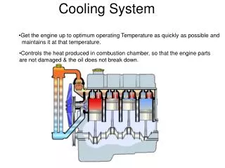
DESIGN REQUIREMENT CYLIDRICAL WALL 40 mm Cooling system Supporting plate FLAT WALL 10 mm Heat flux • SHARING THE JOBS : • CYLINDRICAL WALLS SUPPORTING THE PRESSURE • FLAT WALLS DEFINING THE FLOW CROSS SECTION • MATERIAL BUDGET X0 = 0.035 % HEAT FLUX UNIFORM: HF = 2 W/cm2 TEMPERATURE GRADIENT > 30° C • THE DESIGN OF THE DETECTOR REQUIRES TO MINIMIZE THE MATERIAL BUDGET • THE COOLING SYSTEM CONCEPT DESIGN FOLLOWS THE SAME REQUIREMENT Na62 GTK working group meeting, CERN 13-12-2011 Marco Statera
MAKING THE PARTS ALL PARTS MADE BY FERRARA WORKSHOP Na62 GTK working group meeting, CERN 13-12-2011 Marco Statera
MECHANICAL TESTS KAPTON CREEP • working pressure Wp = 1 bar • Test pressure Tp = 2Wp = 2 bar • AFTER TWO WEEKS @ Tp NO EVIDENCE OF CREEP • KAPTON FAILURE PRESSURE • safety factor (40 mm) 2.0 @ Wp • QUALITY OF THE JOINT KAPTON-RESIN-ALUMINUM • safety factor 1.9 Na62 GTK working group meeting, CERN 13-12-2011 Marco Statera
OPTIMIZATION injection channels : share the flow rate & avoid the temperature drop on the inner edge of the detector lateral channels : the flow is injected cooled until the exit Na62 GTK working group meeting, CERN 13-12-2011 Marco Statera
OUTLINE DESIGN CONCEPT AND OPTIMIZATION TEST SETUP RESULTS SYSTEM ASSEMBLY PROCEDURE CONCLUSIONS Na62 GTK working group meeting, CERN 13-12-2011 Marco Statera
ROOM TEMPERATURE MEASUREMENT SILICON WINDOW DETECTOR MOCK UP & DISTRIBUTING CHANNELS THERMO-CAMERA Na62 GTK working group meeting, CERN 13-12-2011 Marco Statera
THERMAL MODEL VALIDATION THERMAL MODEL THERMOCAMERA IMAGE Na62 GTK working group meeting, CERN 13-12-2011 Marco Statera
TEST BENCH AND READOUT FLOW VACUUM TEMPERATURES VS TIME VACUUM POWER & TEMPERATURES FLOW RATE Na62 GTK working group meeting, CERN 13-12-2011 Marco Statera
TEMPERATURE SENSORS T9 T6 T7 T8 T5 FLOW T10 T11 T12 T13 T14 T1 T4 T3 T2 T0 Na62 GTK working group meeting, CERN 13-12-2011 Marco Statera
OUTLINE DESIGN CONCEPT AND OPTIMIZATION TEST SETUP RESULTS SYSTEM ASSEMBLY PROCEDURE CONCLUSIONS Na62 GTK working group meeting, CERN 13-12-2011 Marco Statera
RESULTS - 1 • 32 W – 48 W – 56 W results Pdigital/Psensor = 3.7 • 48 W: different sensor temperatures regulating the flow (4 l/min) Na62 GTK working group meeting, CERN 13-12-2011 Marco Statera
RESULTS- 2 measured temperatures of the sensor area (T10-T14) ΔT < 6° C average temperature regulated by flow (+5° C ÷ -30° C ) Na62 GTK working group meeting, CERN 13-12-2011 Marco Statera
RESULTS - 3 measured temperatures of digital area (T0-T4 and T5-T9) and sensor area (T10-T14) • set sensor and digital temperature @ nominal power <-> flow regulation • reduce max temperature and gradient Na62 GTK working group meeting, CERN 13-12-2011 Marco Statera
TYPICAL MEASUREMENT - 1 sensor temperature regulation by flow at different powers Na62 GTK working group meeting, CERN 13-12-2011 Marco Statera
TYPICAL MEASUREMENT - 2 4 W -> 56 W Pdig/Psens=3.7 32 WPdig/Psens=3.7 the system is optimized for the asymmetric power distribution Na62 GTK working group meeting, CERN 13-12-2011 Marco Statera
HEATERS & MATERIAL • effect on temperature distribution • local power distribution • material thermal properties digital resistance measured values [Ω] before and after the test of mockup #11 avg = 55.3 Ω std = 6.3 Ω Na62 GTK working group meeting, CERN 13-12-2011 Marco Statera
EXTRAPOLATION resistor spread increases longitudinal and trasversal gradient given a flow and power Ti = T x Ri / 60 Ri measured; 60 Ω nominal R; correction (extrapolation) up to 20° C Na62 GTK working group meeting, CERN 13-12-2011 Marco Statera
OUTLINE DESIGN CONCEPT AND OPTIMIZATION TEST SETUP RESULTS SYSTEM ASSEMBLY PROCEDURE CONCLUSIONS Na62 GTK working group meeting, CERN 13-12-2011 Marco Statera
THE SYSTEM • COOLING: • GAS FROM LIQUID • THE SYSTEM • how it works and costs • RUN AND MAINTENANCE • PROCEDURES • pumpdown, cooldown, time constants : fast ramp up/down, emergency warm up, 1 heater broken • INTERLOCK Na62 GTK working group meeting, CERN 13-12-2011 Marco Statera
GAS FROM LIQUID • the gas above a liquidbathisforcedinto the coolingpipes and cooled down by a cold head • the pressureof the dewariskeptconstant; a heater at the cold head alsoprevents low pressures • the flow isregulatedby the valve • additionalrelief valve • Pro • liquid is a reserve of gas • fast restart time after an emergency stop • cooling power: 170 W @ 77K • safe shut off: the emergency valve reduces the dewar pressure • Cons • needs cryogenic liquid • pumping vapor • COST • 4 systems: 370 k€ Na62 GTK working group meeting, CERN 13-12-2011 Marco Statera
THE SYSTEM • gas from liquid solution is proposed • three stations: one coling station is not cheaper since the cost of the cryogenic lines. Three pumping/cooling systems are required • each station is independent (no crosstalks) • Installation side: Jura or Saleve • 20 m of cryogenic lines: • the cooling station few meters far from the beampipe • the outer diameter is about 35 mm, we asked for a 100x100 mm2 cross section in the trench • the control system (PLC) is outside the cavern Na62 GTK working group meeting, CERN 13-12-2011 Marco Statera
RUN AND MAINTENANCE RUN refill liquid nitrogen start the coldhead emergency stop -> some nitrogen gas lost; the liquid is a reserve. NO access required 6 months running SAFETY cryostat: pressurized vessel cold nitrogen standard issues to be discussed with lab safety staff MAINTENANCEevery 9000 hrs (12 months run) coldhead maintenance (2 skilled persons for 2 days): head o-ring kit and compressor filters valvescheck (emergency test) Na62 GTK working group meeting, CERN 13-12-2011 Marco Statera
PROCEDURES pumpdown cooldown turning on and regulation warmup one chip failure emergency Na62 GTK working group meeting, CERN 13-12-2011 Marco Statera
PUMPDOWN • turbopump nominal pumping speed: 70 l/s (N2) • typical working pressure < 1 E-5 mbar • Improve vacuum performance: faster pumpdown and lower ultimate pressure • accurate handling/cleaning • UHV materials • vacuum before installing Na62 GTK working group meeting, CERN 13-12-2011 Marco Statera
COOLDOWN 29-11-2011 COOLDOWN TEMPERATURES AND FLOW stable cooldown conditions set temperature and cooling speed by flow regulation i.e. regualting the valve Na62 GTK working group meeting, CERN 13-12-2011 Marco Statera
TURN ON AND REGULATION + 8 W (16 –> 24 W) ΔT 25 °C in 35 s the full digital power on (48 W) requires control (heater) regulating the flow 10 seconds compatible with a few seconds full on/off valve Na62 GTK working group meeting, CERN 13-12-2011 Marco Statera
TURN ON PROCEDURE a heater resistor is required (on the N2 line) use of an additional temperature sensor (a TC not on the sensor) increase the flow regulating the board temperature by the heater -> nominal flow (sensor temperature > -20 Celsius) turn on the sensors and turn off the heater regulate the SENSOR temperature by the valve (flow) Na62 GTK working group meeting, CERN 13-12-2011 Marco Statera
WARM UPAND CHIP FAILURE • self warm up – cooling turned off • max warming speed about 40 K/h • external heating not required • temperature drop in case the heater (chip) fails is about 10 Degrees @ power 32 W • the system reads one temperature, may change the flow and/or set an allarm Na62 GTK working group meeting, CERN 13-12-2011 Marco Statera
EMERGENCY May 2011 • about 25 seconds with the valve closed: temperature rise 4 K/s • @25 seconds power is stopped • no need of very fast interlock: about 1 second Na62 GTK working group meeting, CERN 13-12-2011 Marco Statera
INTERLOCK • INPUT (4) • sensor temperature (average or 1 point) • TC on the board (requested) • chip power supply current • emergency signal • CONTROL • regulating valve opening (flow) • gas heater • bypass valve (cryostat) • coldhead + coldhead heater • OUTPUT (3) • sensor temperature (crosscheck) • regulating valve opening • status (OK/alarm) • PLC (fully hardware – interlock & control) • outside the cavern • no interaction during run • RATE: about 1Hz (typical 10Hz) Na62 GTK working group meeting, CERN 13-12-2011 Marco Statera
PROGRAMS • COOLDOWN • stable flow (i.e. valve opening) • regulating temperature by TC on the board • STANDBY • preparation before run and after run • TC on the board useful • RUN • control loop: Si temperature <-> valve opening • WARM UP • EMERGENCY • close the regulating valve (normally closed) • open the safety valve of the dewar (1 atm in seconds) • turn off the cryohead (and heating to room temperature if possible) • emergency signal output Na62 GTK working group meeting, CERN 13-12-2011 Marco Statera
OUTLINE DESIGN CONCEPT AND OPTIMIZATION TEST SETUP RESULTS SYSTEM ASSEMBLY PROCEDURE CONCLUSIONS Na62 GTK working group meeting, CERN 13-12-2011 Marco Statera
INTEGRATION – PHASE 1 mask aligner : the supports are inserted in the reference places SLIDING SUPPORT GUIDES TEFLON MASK ALIGNER FIXED SUPPORT UNDERCUT FITTING THE PCB THICKNESS Na62 GTK working group meeting, CERN 13-12-2011 Marco Statera
INTEGRATION – PHASE 2 Mounting the mask aligner in the PCB supporting plate SLIDING SUPPORT GUIDES & FIXED SUPPORT REFERENCE PINS TEFLON MASK ALIGNER PCB SUPPORTING PLATE TEFLON MASK ALIGNER SEAT Na62 GTK working group meeting, CERN 13-12-2011 Marco Statera
INTEGRATION – PHASE 3 Glueing the sliding support guides and the fixed support on the PCB REFERENCE PINS MASK ALIGNER PCB SUPPORTING PLATE Na62 GTK working group meeting, CERN 13-12-2011 Marco Statera
INTEGRATION – PHASE 4 inserting the sliding support after the resin curing SLIDING SUPPORTS PCB Na62 GTK working group meeting, CERN 13-12-2011 Marco Statera
INTEGRATION – PHASE 5 mounting PCB & detector supports on The PCB support plate PCB DETECTOR SUPPORTS PCB SUPPORT PLATE Na62 GTK working group meeting, CERN 13-12-2011 Marco Statera
INTEGRATION – PHASE 6 gluing the detector on the detector supports PCB DETECTOR REFERENCE PINS DETECTOR SUPPORTS DETECTOR REFENCE UNDERCUT PCB SUPPORT PLATE Na62 GTK working group meeting, CERN 13-12-2011 Marco Statera
INTEGRATION – PHASE 7 The centre of the detector is referred outside the vacuum vessel OUTHER REFERENCE CENTRE OF THE DETECTOR INNER REFERENCE CENTRE OF THE DETECTOR DETECTOR CENTRE (NOMINAL) Na62 GTK working group meeting, CERN 13-12-2011 Marco Statera
INTEGRATION – PHASE 8 bonding the wires WIRE BONDS Na62 GTK working group meeting, CERN 13-12-2011 Marco Statera
INTEGRATION – PHASE 9 ASSEMBLING THE TWO HALF VESSELS Na62 GTK working group meeting, CERN 13-12-2011 Marco Statera
INTEGRATION – PHASE 10 MOUNTING THE TUBES Na62 GTK working group meeting, CERN 13-12-2011 Marco Statera
TEST OF THE PCB & DETECTOR ASSEMBLY PROCEDURE THERMAL SHOCK ROOM TEMPERATURE TO 77 K Na62 GTK working group meeting, CERN 13-12-2011 Marco Statera
TEAM design, simulation, tests, development & construction Manuel BOLOGNESI (electr. service) Stefano CHIOZZI (electr. service) Angelo COTTA RAMUSINO (electr. service) Luca LANDI (mech. service) Roberto MALAGUTI (electr. service) Michele MELCHIORRI (mech. service) Claudio PADOAN (electr. service) Stefano SQUERZANTI (mech. service) Ferruccio PETRUCCI Vittore CARASSITI (mech. service) Marco STATERA (vacuum & cryo service) Na62 GTK working group meeting, CERN 13-12-2011 Marco Statera
CONCLUSIONS -1 • design concept and optimization • mechanical design and test: safety factor >2 • material budget Xo = 0.035 % • optimization • room temperature and working condition test benches • FEM flow simulation validated • the results we have shown • the final prototype tested in working conditions: power, power distribution, temperature and vacuum • the system has been tested up to 56 W (actual power distribution) • regulation of the sensor temperature by the flow rate: 0 ÷ -20° C @ 48 W • the system can work with different power distributions: 32 W homogeneus power distribution results Na62 GTK working group meeting, CERN 13-12-2011 Marco Statera
CONCLUSIONS - 2 • system overview • cooling method: gas from liquid nitrogen • installation requirements • no access required during a full run • measured parameters for different working states • control and interlock • input/output defined • running programs defined • interlock conceptual design for different working states • integration • realistic integration sequence • three points holder assembled and tested in severe thermal conditions Na62 GTK working group meeting, CERN 13-12-2011 Marco Statera