Download
1 / 84
840 likes | 1.02k Views
2. Objectives. Explain basic data transmission concepts, including full duplexing, attenuation, latency, and noiseDescribe the physical characteristics of coaxial cable, STP, UTP, and fiber-optic mediaCompare the benefits and limitations of different networking mediaExplain the principles behind

E N D
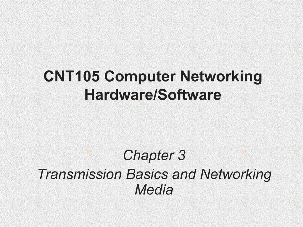
1. CNT105 Computer Networking Hardware/Software Chapter 3
Transmission Basics and Networking Media
2. 2 Objectives Explain basic data transmission concepts, including full duplexing, attenuation, latency, and noise
Describe the physical characteristics of coaxial cable, STP, UTP, and fiber-optic media
Compare the benefits and limitations of different networking media
Explain the principles behind and uses for serial connector cables
Identify wiring standards and the best practices for cabling buildings and work areas
3. 3 Transmission Basics Transmit
Issue signals along network medium
Transmission
Process of transmitting
Signal progress after transmitted
Transceiver
Transmit and receive signals
4. 4 Analog and Digital Signaling Important data transmission characteristic
Signaling type: analog or digital
Volt
Electrical current pressure
Electrical signal strength
Directly proportional to voltage
Signal voltage
Signals
Current, light pulses, electromagnetic waves
5. 5 Analog data signals
Voltage varies continuously
Properties
Amplitude, frequency, wavelength, phase
6. 6 Analog and Digital Signaling (cont�d.) Amplitude
Analog wave�s strength
Frequency
Number of times amplitude cycles over fixed time period
Measure in hertz (Hz)
Wavelength
Distance between corresponding wave cycle points
Inversely proportional to frequency
Expressed in meters or feet
7. 7 Phase
Wave�s progress over time in relationship to fixed point
8. 8 Analog and Digital Signaling (cont�d.) Analog signal benefit over digital
More variable
Convey greater subtleties with less energy
Drawback of analog signals
Varied and imprecise voltage
Susceptible to transmission flaws
Digital signals
Pulses of voltages
Positive voltage represents a 1
Zero voltage represents a 0
9. 9 Binary system
1s and 0s represent information
Bit (binary digit)
Possible values: 1 or 0
Digital signal pulse
10. 10 Byte
Eight bits together
Computers read and write information
Using bits and bytes
Find decimal value of a bit
Multiply the 1 or 0 by 2x (x equals bit�s position)
11. 11 Analog and Digital Signaling (cont�d.) Convert byte to decimal number
Determine value represented by each bit
Add values
Convert decimal number to a byte
Reverse the process
Convert between binary and decimal
By hand or calculator
12. 12 Analog and Digital Signaling (cont�d.) Digital signal benefit over analog signal
More reliable
Less severe noise interference
Digital signal drawback
Many pulses required to transmit same information
Overhead
Nondata information
Required for proper signal routing and interpretation
13. 13 Data Modulation Data relies on digital transmission
Network connection may handle only analog signals
Modem
Accomplishes translation
Modulator/demodulator
Data modulation
Technology modifying analog signals
Make data suitable for carrying over communication path
14. 14 Data Modulation (cont�d.) Carrier wave
Combined with another analog signal
Produces unique signal
Transmitted from one node to another
Preset properties
Purpose
Convey information
Information wave (data wave)
Added to carrier wave
Modifies one carrier wave property
15. 15 Data Modulation (cont�d.) Frequency modulation
Carrier frequency modified
By application of data signal
Amplitude modulation
Carrier signal amplitude modified
By application of data signal
16. 16
17. 17 Simplex, Half-Duplex, and Duplex Simplex
Signal transmission: one direction
Half-duplex transmission
Signal transmission: both directions
One at a time
One communication channel
Shared for multiple nodes to exchange information
Full-duplex
Signals transmission: both directions simultaneously
Used on data networks
18. 18 Channel
Distinct communication path between nodes
Separated physically or logically
Full duplex advantage
Increases speed
19. 19 Multiplexing Multiplexing
Multiple signals
Travel simultaneously over one medium
Subchannels
Logical multiple smaller channels
Multiplexer (mux)
Combines many channel signals
Demultiplexer (demux)
Separates combined signals
Regenerates them
20. 20 TDM (time division multiplexing)
Divides channel into multiple time intervals
21. 21 Statistical multiplexing
Transmitter assigns slots to nodes
According to priority, need
More efficient than TDM
22. 22 FDM (frequency division multiplexing)
Unique frequency band for each communications subchannel
Two types
Cellular telephone transmission
DSL Internet access
23. 23 WDM (wavelength division multiplexing)
One fiber-optic connection
Carries multiple light signals simultaneously
DWDM (dense wavelength division multiplexing)
Used on most modern fiber-optic networks
Extraordinary capacity
24. 24 Relationships Between Nodes Point-to-point transmission
One transmitter and one receiver
Point-to-multipoint transmission
One transmitter and multiple receivers
Broadcast transmission
One transmitter and multiple, undefined receivers
Used on wired and wireless networks
Simple and quick
Nonbroadcast
One transmitter and multiple, defined receivers
25. 25 Relationships Between Nodes (cont�d.)
26. 26 Throughput and Bandwidth Throughput
Measures amount of data transmitted
During given time period
Capacity or bandwidth
Quantity of bits transmitted per second
Bandwidth (strict definition)
Measures difference between highest and lowest frequencies medium can transmit
Range of frequencies
Measured in hertz (Hz)
27. 27 Throughput and Bandwidth (cont�d.)
28. 28 Baseband and Broadband Baseband transmission
Digital signals sent through direct current (DC) pulses applied to wire
Requires exclusive use of wire�s capacity
Transmit one signal (channel) at a time
Example: Ethernet
Broadband transmission
Signals modulated
Radiofrequency (RF) analog waves
Uses different frequency ranges
Does not encode information as digital pulses
29. 29 Transmission Flaws Noise
Any undesirable influence degrading or distorting signal
Types of noise
EMI (electromagnetic interference)
EMI/RFI (radiofrequency interference)
Cross talk
NEXT (near end cross talk)
Potential cause: improper termination
Environmental influences
Heat
30. 30 Transmission Flaws (cont�d.)
31. 31 Transmission Flaws (cont�d.) Attenuation
Loss of signal�s strength as it travels away from source
Signal boosting technology
Analog signals pass through amplifier
Noise also amplified
Regeneration
Digital signals retransmitted in original form
Repeater: device regenerating digital signals
Amplifiers and repeaters
OSI model Physical layer
32. 32
33. 33 Transmission Flaws (cont�d.) Latency
Delay between signal transmission and receipt
Causes
Cable length
Intervening connectivity device
RTT (round trip time)
Time for packet to go from sender to receiver, then back from receiver to sender
Measured in milliseconds
May cause network transmission errors
34. 34 Common Media Characteristics Selecting transmission media
Match networking needs with media characteristics
Physical media characteristics
Throughput
Cost
Size and scalability
Connectors
Noise immunity
35. 35 Throughput Most significant transmission method factor
Causes of limitations
Laws of physics
Signaling and multiplexing techniques
Noise
Devices connected to transmission medium
Fiber-optic cables allows faster throughput
Compared to copper or wireless connections
36. 36 Cost Precise costs difficult to pinpoint
Media cost dependencies
Existing hardware, network size, labor costs
Variables influencing final cost
Installation cost
New infrastructure cost versus reuse
Maintenance and support costs
Cost of lower transmission rate affecting productivity
Cost of obsolescence
37. 37 Noise Immunity Noise distorts data signals
Distortion rate dependent upon transmission media
Fiber-optic: least susceptible to noise
Limit impact on network
Cable installation
Far away from powerful electromagnetic forces
Select media protecting signal from noise
Antinoise algorithms
38. 38 Size and Scalability Three specifications
Maximum nodes per segment
Maximum segment length
Maximum network length
Maximum nodes per segment dependency
Attenuation and latency
Maximum segment length dependency
Attenuation and latency plus segment type
39. 39 Size and Scalability (cont�d.) Segment types
Populated: contains end nodes
Unpopulated: No end nodes
Link segment
Segment length limitation
After certain distance, signal loses strength
Cannot be accurately interpreted
40. 40 Connectors and Media Converters Connectors
Hardware connecting wire to network device
Specific to particular media type
Affect costs
Installing and maintaining network
Ease of adding new segments or nodes
Technical expertise required to maintain network
Media converter
Hardware enabling networks or segments running on different media to interconnect and exchange signals
41. 41 Connectors and Media Converters (cont�d.)
42. 42 Coaxial Cable Central metal core (often copper)
Surrounded by insulator
Braided metal shielding (braiding or shield)
Outer cover (sheath or jacket)
43. 43 Coaxial Cable (cont�d.) High noise resistance
Advantage over twisted pair cabling
Carry signals farther before amplifier required
Disadvantage over twisted pair cabling
More expensive
Hundreds of specifications
RG specification number
Differences: shielding and conducting cores
Transmission characteristics
44. Coaxial Cable (cont�d.) Conducting core
American Wire Gauge (AWG) size
Data networks usage
RG-6
RG-8
RG-58
RG-59 44
45. 45 Coaxial Cable (cont�d.)
46. 46 Twisted Pair Cable Color-coded insulated copper wire pairs
0.4 to 0.8 mm diameter
Encased in a plastic sheath
47. 47 Twisted Pair Cable (cont�d.) More wire pair twists per foot
More resistance to cross talk
Higher-quality
More expensive
Twist ratio
Twists per meter or foot
High twist ratio
Greater attenuation
48. 48 Twisted Pair Cable (cont�d.) Hundreds of different designs
Dependencies
Twist ratio, number of wire pairs, copper grade, shielding type, shielding materials
1 to 4200 wire pairs possible
Wiring standard specification
TIA/EIA 568
Twisted pair wiring types
Cat (category) 3, 4, 5, 5e, 6, and 6e, Cat 7
CAT 5 most often used in modern LANs
49. 49 Twisted Pair Cable (cont�d.) Advantages
Relatively inexpensive
Flexible
Easy installation
Spans significant distance before requiring repeater
Accommodates several different topologies
Handles current faster networking transmission rates
Two categories
STP (shielded twisted pair)
UTP (unshielded twisted pair)
50. STP (Shielded Twisted Pair) Individually insulated
Surrounded by metallic substance shielding (foil)
Barrier to external electromagnetic forces
Contains electrical energy of signals inside
May be grounded 50
51. 51 UTP (Unshielded Twisted Pair) One or more insulated wire pairs
Encased in plastic sheath
No additional shielding
Less expensive, less noise resistance
52. 52 UTP (Unshielded Twisted Pair) (cont�d.) EIA/TIA standards
Cat 3 (Category 3)
Cat 4 (Category 4)
Cat 5 (Category 5)
Cat 5e (Enhanced Category 5)
Cat 6 (Category 6)
Cat 6e (Enhanced Category 6)
Cat 7 (Category 7)
53. 53 UTP (Unshielded Twisted Pair) (cont�d.)
54. 54 Comparing STP and UTP Throughput
STP and UTP transmit the same rates
Cost
STP and UTP vary
Noise immunity
STP more noise resistant
UTP subject to techniques to offset noise
Size and scalability
STP and UTP maximum segment length
100 meters
55. 55 Comparing STP and UTP (cont�d.) Connector
STP and UTP use RJ-45 (Registered Jack 45)
Telephone connections use RJ-11 (Registered Jack 11)
56. 56 Terminating Twisted Pair Cable Patch cable
Relatively short cable
Connectors at both ends
Proper cable termination techniques
Basic requirement for two nodes to communicate
Poor terminations
Lead to loss or noise
TIA/EIA standards
TIA/EIA 568A
TIA/EIA 568B
57. 57
58. Straight-through cable
Terminate RJ-45 plugs at both ends identically
Crossover cable
Transmit and receive wires on one end reversed 58
59. 59 Terminating Twisted Pair Cable (cont�d.) Termination tools
Wire cutter
Wire stripper
Crimping tool
60. 60 Terminating Twisted Pair Cable (cont�d.) After making cables
Verify data transmit and receive
61. 61 Fiber-Optic Cable Fiber-optic cable (fiber)
One (or several) glass or plastic fibers at its center (core)
Data transmission
Pulsing light sent from laser
LED (light-emitting diode) through central fibers
Cladding
Layer of glass or plastic surrounding fibers
Different density from glass or plastic in strands
Reflects light back to core
Allows fiber to bend
62. 62 Fiber-Optic Cable (cont�d.) Plastic buffer
Outside cladding
Protects cladding and core
Opaque
Absorbs any escaping light
Kevlar strands (polymeric fiber) surround plastic buffer
Plastic sheath covers Kevlar strands
63. Different varieties
Based on intended use and manufacturer
Two categories
Single-mode
Multimode 63
64. 64 SMF (Single-Mode Fiber) Uses narrow core (< 10 microns in diameter)
Laser generated light travels over one path
Little reflection
Light does not disperse
Accommodates
Highest bandwidths, longest distances
Connects carrier�s two facilities
Costs prohibit typical LANs, WANs use
65. 65 SMF (Single-Mode Fiber) (cont�d.)
66. 66 MMF (Multimode Fiber) Uses core with larger diameter than single-mode fiber
Common size: 62.5 microns
Laser or LED generated light pulses travel at different angles
Common uses
Cables connecting router to a switch
Cables connecting server on network backbone
67. 67 MMF (Multimode Fiber) (cont�d.)
68. 68 MMF (Multimode Fiber) (cont�d.) Benefits
Extremely high throughput
Very high resistance to noise
Excellent security
Ability to carry signals for much longer distances before requiring repeaters than copper cable
Industry standard for high-speed networking
Drawback
More expensive than twisted pair cable
Requires special equipment to splice
69. 69 MMF (Multimode Fiber) (cont�d.) Throughput
Reliable transmission rates
Can reach 100 gigabits (or 100,000 megabits) per second per channel
Cost
Most expensive transmission medium
Connectors
ST (straight tip)
SC (subscriber connector or standard connector)
LC (local connector)
MT-RJ (mechanical transfer registered jack)
70. 70 MMF (Multimode Fiber) (cont�d.) Noise immunity
Unaffected by EMI
Size and scalability
Segment lengths vary
150 to 40,000 meters
Due primarily to optical loss
71. 71
72. 72 DTE (Data Terminal Equipment) and DCE (Data Circuit-Terminating Equipment) Connector Cables DTE (data terminal equipment)
Any end-user device
DCE (data circuit-terminating equipment)
Device that processes signals
Supplies synchronization clock signal
73. DTE and DCE Connector Cables (cont�d.) DTE and DCE connections
Serial
Pulses flow along single transmission line
Sequentially
Serial cable
Carries serial transmissions 73
74. 74 DTE and DCE Connector Cables (cont�d.)
75. 75 DTE and DCE Connector Cables (cont�d.) RS-232 (Recommended Standard 232)
EIA/TIA standard
Physical layer specification
Signal voltage, timing, compatible interface characteristics
Connector types
RJ-45 connectors, DB-9 connectors, DB-25 connectors
RS-232 used between PC and router today
RS-232 connections
Straight-through, crossover, rollover
76. 76 Structured Cabling Cable plant
Hardware making up enterprise-wide cabling system
Standard
TIA/EIA joint 568 Commercial Building Wiring Standard
77. 77
78. 78
79. 79 Structured Cabling (cont�d.) Components
Entrance facilities
MDF (main distribution frame)
Cross-connect facilities
IDF (intermediate distribution frame)
Backbone wiring
Telecommunications closet
Horizontal wiring
Work area
80. 80
81. 81 Structured Cabling (cont�d.)
82. 82
83. 83 Best Practices for Cable Installation and Management Choosing correct cabling
Follow manufacturers� installation guidelines
Follow TIA/EIA standards
Network problems
Often traced to poor cable installation techniques
Installation tips to prevent Physical layer failures
84. 84 Summary Transmission methods
Analog or digital
Data modulation
Multiplexing
Basic data transmission concepts
Full duplexing, attenuation, latency, noise
Transmission flaws
Noise, attenuation, latency
85. 85 Summary (cont�d.) Media characteristics
Throughput, cost, size and scalability, connectors, noise immunity Media
Coaxial, Twisted pair, Fiber-optic
DTE and DCE connector cables
DB-9 and DB-25
Structured cabling
TIA/EIA joint 568 Commercial Building Wiring Standard
Components
Best practices