Download
1 / 24
300 likes | 538 Views
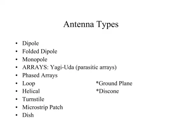
Panel Antenna. Design Review: November 17,2011 Team Members: Allan Davis Carlos Gonzalez Cooper McBride. Objective. Design, fabricate and test a 900-Mhz directional panel antenna for Schweitzer Engineering Laboratories. Applications.

E N D
Panel Antenna Design Review: November 17,2011 Team Members: Allan Davis Carlos Gonzalez Cooper McBride
Objective • Design, fabricate and test a 900-Mhz directional panel antenna for Schweitzer Engineering Laboratories
Applications • Radios provide comm channels for electric utility protection, monitoring, and control • Economical alternative to fiber-optic cable • Backup primary protection channels
Other Uses • Oil and gas pipelines and refineries • Water and wastewater treatment facilities • Fire and security alarm remote monitoring • Many more possible applications of wireless communications for critical infrastructure
What SEL Needs • An antenna that will have performance similar to a 5-element Yagi antenna • The antenna will be used with the SEL-3031 transceiver
Why a Panel Antenna? • SEL is currently selling directional Yagi antennas • An example of a 5-element Yagi is shown here
Panel Antenna Pros: • Lower cost than Yagi • Compact package • Ease of installation • SEL can manufacture a panel antenna using existing facilities and equipment • Panel Antenna Cons: • Can’t increase directivity by adding elements as with Yagi • More ways for material inconsistencies to affect performance
Specifications • Directional • Vertical or Horizontal Polarization • Gain: ≥8 dBi • HP Horizontal Beamwidth: 45° • HP Vertical Beamwidth: 65° • Operating Frequency Range: 900-930 MHz • ~ 3% Bandwidth • VSWR: ≤1.5:1 • Characteristic Impedance: 50 Ω • Designed Using Printed Circuit Board Technology
Example Radiation Patterns Dipole Yagi
Current Design - Bowtie • This is a type of planar dipole antenna • θ0 is called the opening angle
Bowtie Formulas • Characteristic impedance* • ZC = ln[cot(θ0 /4)] • Length* • L = 0.5 λ0 /(εeff)1/2 • Effective dielectric constant* • εeff = 0.5(εr + 1) + 0.5(εr – 1)(1 + 10 d/W)-0.555 • We plan to use FR-4 substrate • εr ~ 4.0-4.8 (decreases as frequency increases) • d is typically 1.6 mm, but other thicknesses available *Source: C. Guo and R. Liu. (2009, June). A 900MHz shielded bow-tie antenna system for ground penetrating radar. [Online]. Available: http://ieeexplore.ieee.org/xpls/abs_all.jsp?arnumber=5550125&tag=1
Possible Design Options • Edge cutting can be used to increase bandwidth of bowtie and decrease physical size
Metal Patch antenna • Gain not very high • Not very robust
Design Challenges • How much gain can we get? • Feeding the antenna • Impedance matching • Determining spacing between PCB and backplate • Correctly interpreting simulation results • Simulation will require a lot of trial and error
Impedance Matching • Want to match impedances to minimize transmission line reflections from antenna toward radio • Max Power Transfer • Low reflection coeff. Low VSWR • This can be done both by changing antenna feed point and by designing microstrip feedline impedance to be Zmicrostrip = (ZcoaxZant)1/2
Validation • Conduct impedance analysis using network analyzers in Applied EM Waves Lab. • Time reserved for use of anechoic chamber at SEL • Use to make antenna pattern measurements • 900-MHz feed & measurement system available (antenna, signal generator, network analyzer, etc.) • Most of our measurements will be focused on figures of merit, since SEL will have to have the antenna characterized before production
Software • Agilent Advanced Design System (ADS) with Electromagnetic Professional (EMPro) • SEL is planning to incorporate ADS Design Suite for future projects • FEM Simulator • FDTD Simulator • Method of Moments • Impedance Analysis
Progress • Currently a little behind according to our timeline • Issue with EMPro software • The software is unable to work correctly with standard Intel Graphic Chipsets • Needed to order an Nvidia graphics card and install into a laboratory computer • Works great now • In the future we will want to upgrade the RAM from 2GB to 4GB
Working on getting tutorials to learn the software • Need to wait for the University license instead of our trial version to obtain access to the tutorials • Have put in our order for the University license
Budget • EMPro Software -$2000 • Nvidia GT 430 Graphics Card - $85 • Kingston 2GB RAM - $25 • N-Connectors - $4 Each • PC Board and metal back plate • Provided by SEL