Download
1 / 17
170 likes | 233 Views
Proposal for the SPL Chopper Structure F. Caspers and A. Mostacci. Potential difficulties related to earlier designs (radiation aspects, out-gassing, size) What could we do in order to reduce the cost for the puls generator or RF–amplifier?

E N D
Proposal for the SPL Chopper StructureF. Caspers and A. Mostacci • Potential difficulties related to earlier designs (radiation aspects, out-gassing, size) • What could we do in order to reduce the cost for the puls generator or RF–amplifier? • Are there other aspects, which would make an alternative design interesting? • Discussion of layout and results • Conclusion Caspers/Mostacci:Proposal for the SPL chopper structure
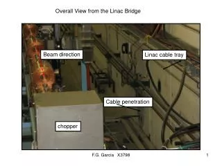
Potential difficulties related to earlier designs (radiation aspects, out-gassing, size) • In previous reports a beam transmission efficiency around 95% over the chopper section has been quoted • Translating these numbers for the SPL (average beam power in the chopper section =4 kW) we would get about 200 Watt beam losses • In the CERN-SPL chopping line (L=6 meter) 1.5 meter are occupied by chopper structures (present version) • The substrate material proposed and used (Rogers RT duroid 6002) contains teflon; out-gassing?! • The radiation limit for teflon in vacuum is 105 Gray (1Gray = 1 Joule/Kg) Caspers/Mostacci:Proposal for the SPL chopper structure
How to reduce the cost for the driver?(impuls generator or wide-band amplifier) • For a 2 ns rise- and fall-time (10%-90%) the external drivers could become very costly for a deflection voltage of 0-1 kV (peak, uni-polar) per deflecting plate.(1 kV into 50 Ohm requires 20 A !; for 500 Volt we still get 10A) • If we could produce deflecting structures with a width of, say, less than 5 cm, they would rather easily fit into dipole or quad magnets and we could simplify the design of this section. • We gain linear (in terms of kicker output power) with the length of the deflecting structures used. • Less voltage per kicker module would simplify the driver design (less signal combination thus better rise/fall time) and lowers the heat loss in the meander. Caspers/Mostacci:Proposal for the SPL chopper structure
An alternative design for a meander structure on aluminum oxide (1) • Using alumina (eps=9.6) on a massive metallic support (e.g. aluminum) would increase the heat transfer capability, allow for less width and has “infinite” radiation resistance • A recent printed version on organic substrates with separators had a width of 90 mm for =0.065 (2 MeV). For=0.08 (3 MeV) a width of 75 mm or somewhat less appears possible with that technology. • With an alumina substrate for =0.08 a width of 45 mm can be reached. • However: Can we get acceptable values for reflection, loss and dispersion when taking alumina? • Are there technological limits to produce printed meander structures on 50 cm long alumina strips? Caspers/Mostacci:Proposal for the SPL chopper structure
An alternative design for a meander structure on aluminum oxide (2) • The concept of separating ridges would be very hard to implement for a ceramic substrate. Thus we have to check the influence of mutual coupling from adjacent lines on the dispersion (variation of group delay vs frequency) • We have to find an optimum for the thickness of the alumina substrate. If it is too thin, it will become very fragile and the conductor losses increase due to the small width of the lines. If its too thick, the mutual coupling from adjacent lines increases. • Reducing the length of the coupling section between adjacent lines should help to reduce dispersion. • Thus a design using a symmetric double meander is proposed ( a simple meander was proposed earlier) Caspers/Mostacci:Proposal for the SPL chopper structure
198+2mm (33 cells) • We are considering first a double meander structure 20 cm long as shown below: 50 mm Substrate: W 3 mm (50 ) 3 mm thick e = 9.6 0.45 mm 6 mm W (100 ) 42.5 mm Caspers/Mostacci:Proposal for the SPL chopper structure
Results for the 20 cm long structure (no additional electro-deposited metal after firing, 0-1GHz);DC resistance near 5 Ohm(= too high) Caspers/Mostacci:Proposal for the SPL chopper structure
50 cm long structure, transmission measurements, 0-600MHz, time -domain display • The metal thickness of the meander has been increased to about 40 micron by electro-chemical deposition 1.65ns 1.98ns Caspers/Mostacci:Proposal for the SPL chopper structure
50 cm long structure,transmission measurements, 0-1000MHz, time-domain display (notice the increased ringing due to larger bandwidth) Caspers/Mostacci:Proposal for the SPL chopper structure
50 cm long LANL structure, measured time domain response, EPAC paper 2000 by S.Kurennoy, 1 ns filter 2 ns filter Caspers/Mostacci:Proposal for the SPL chopper structure
50 cm long structure,transmission measurements, 0-1000MHz; for comparison, on the right, meas data from LANL, Kurennoy, EPAC2000 [also 50 cm long but on RT duroid substrate with separating fins] Caspers/Mostacci:Proposal for the SPL chopper structure
50 cm long structure,transmission measurements, 0-1000 MHz, phase after delay correction Caspers/Mostacci:Proposal for the SPL chopper structure
50 cm long structure,transmission measurement, 0-1000 MHz, group delay variation vs frequency Caspers/Mostacci:Proposal for the SPL chopper structure
50 cm long structure, reflection measurement, S11 (step-response) in the time domain (0-1000 MHz bandwidth) • notice, that the char. impedance is slightly too low (about 46 Ohm instead of 50 Ohm) Caspers/Mostacci:Proposal for the SPL chopper structure
50 cm long structure, field coverage factor (data provided by S.Kurennoy) peak value on axis =0.79 for the 50 Ohm meander in upper color bar. Relative color scale up to 100 % Caspers/Mostacci:Proposal for the SPL chopper structure
50 cm long structure, field coverage factor (data provided by S.Kurennoy), 100 Ohm structure, peak value=0.74 Caspers/Mostacci:Proposal for the SPL chopper structure
Conclusion • This prototype of a 50 ohm double meander printed on 3 mm thick alumina is a competitive candidate for the SPL chopper • Losses and dispersion are comparable to the LANL prototype • The structure can stand the radiation and heat load (if water cooled) and should have good vacuum properties • Wideband impedance matching can be achieved • The field coverage factor is slightly lower(79%) as compared to the LANL prototype (89% ) for 50 Ohm impedance. • 100 Ohm char. impedance is also possible, but at the expense of further decrease in field coverage as well as in field homogeneity Caspers/Mostacci:Proposal for the SPL chopper structure