Download
1 / 25
250 likes | 376 Views
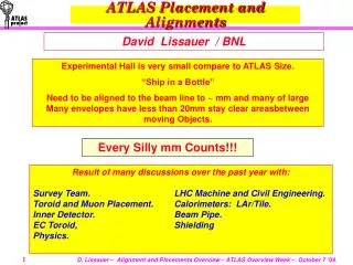
ATLAS Placement and Alignments. David Lissauer / BNL. Experimental Hall is very small compare to ATLAS Size. “Ship in a Bottle” Need to be aligned to the beam line to ~ mm and many of large Many envelopes have less than 20mm stay clear areasbetween moving Objects. Every Silly mm Counts!!!.

E N D
ATLAS Placement and Alignments David Lissauer / BNL Experimental Hall is very small compare to ATLAS Size. “Ship in a Bottle” Need to be aligned to the beam line to ~ mm and many of large Many envelopes have less than 20mm stay clear areasbetween moving Objects. Every Silly mm Counts!!! Result of many discussions over the past year with: Survey Team. LHC Machine and Civil Engineering. Toroid and Muon Placement. Calorimeters: LAr/Tile. Inner Detector. Beam Pipe. EC Toroid, Shielding Physics.
ATLAS Placement Considerations Items under active consideration: Floor Stability -- Monitoring on going HO/HS Structures -- Accepted Feet & Rail Placement -- Feet Accepted/Final Rail Aug ’05. Barrel Toroid Placement -- Ongoing Barrel Calorimeters/Solenoid -- Ongoing EC Calorimeter -- Under study ID Placement -- Preliminary agreement/Ongoing Beam Pipe Placement -- Preliminary agreement/Ongoing Small Wheel -- Under Study EC Toroid -- Under Study Big Wheels -- Under Study EO Chambers -- Under Study JF Shielding -- Under Study
LHC Nominal Beam and IP. • Nominal Beam Line: • Close orbit calculations uncertainty in the Nominal Beam Line (Geometrical line) is 3 mm. (I.e. actual beam vs. nominal beam line) Uncertainty might be reduced by the time Barrel Calorimeter is installed (’05) • Beam Adjustments : • “Immediate”: < 1 mm by changing the magnetic field in the last magnet. • “Short term”: ~1 mm by adjusting the Jacks under the last triplet. • “Long term”: Re-align a string of magnets along the tunnel. Adjustments could be as much as 10-20 m.m. (K. Potter et al.) • Discussions with Machine, Survey: (K. Potter et al.) • Machine will be able to align itself to the ATLAS experiment to the level of 10-20 mm during a long shut down. The machine does not expect to be able to do this more than once every ~ 3 Years.
Placement Strategy • Stages I: Surface assemblies. • Placement of assemblies on the surface. Components need to be aligned and adjusted relative each other on the surface. • E.g: Barrel Cryostat Assembly: EM calorimeter, Solenoid magnet and Cryostat. • ID Barrel Assembly: Included TRT , SCT and Pixel Tube. • Stage II: Cavern assemblies. • Placement of Assemblies in the Cavern. Components need to be aligned and adjusted relative each other (Geometrical Beam line at the same time). • E.g: Barrel Cal Assembly: Tile and Barrel Cryostat Assembly are aligned relative to each other and the nominal beam line. • Stage III: Final placement. • Placement of assemblies relative to the nominal beam. (Usually) • E.g: Barrel Can Moves to final position and aligned relative to the Nominal Beam. • Barrel Toroid. • Due to the Floor movement we need to decide if we place the object at nominal position of “Off” nominal position expecting floor movement. TC/Survey/Systems follow each of the “assemblies” Working groups follow Placement specifications, and survey needs.
ATLAS Exp. Hall – Floor Movement • Civil Engineering expectation: The existing calculation were done with simplifying assumptions. • Too large of a grid • Uniform Load on the floor • Floor Settlement:-2 mm from the time the concrete if poured and the time ATLAS got possession of the experimental hall. (No measurements to verify this) • ATLAS weight:-5.5 mm (Total –7.5 mm) due to the weight of the exp. Over ~ 6 month. Adiabatic as the weight is added. • Floor upward lift due to Hydrostatic Pressure: ~ + 1 mm / year due to hydrostatic pressure. Up To ~ 20 mm over 20 years.
GRID Monitoring Floor Movement A GRID of Survey “Rivets” has been installed at strategic position. Monitoring of the floor stability is ongoing from July/August of ’03. Expect to re-measure position every 2-6 month. Accuracy : 0.3 mm – ‘datum point’: deep reference in the tunnel (same for machine and experiment geometry)
Hydrostatic Monitoring Hydrostatic System has been operating since June ’04. (See TMB report by Hélène MAINAUD DURAND TS/SU/MTI) Time span is small but measurements indicate movement of the floor. Higher on USA side than US side. (For details see presentation by Jean-Christophe Gayde) Relative height accuracy better than 100 Microns. Absolute (relative to beam line 0.3 mm Sigma)
Hydrostatic data quality Note Scale: In Microns!!
Floor Stability – 8/03 9/04. Precision (1 sigma)of the dZ = 0.2 mm
Floor and Bedplate Stability – 3D Model From 25 June 04 to 08 Sept 04 Floor Movement uneven. Possible combination of Hydrostatics lift and sage due to weight. Need more time dependent data.
Floor Movement – Best Estimate Settlement Due to Cement Contraction before 1st meas. 3 MM Settlement Due to ATLAS Weight. 0.4 MM/year lift Due to hydrostatic pressure Summary of the “pessimistic” prediction for the floor movements.
Feet/ Rails: Installed. Rail: Have been aligned and removed for Toroid installation. Final alignment after Toroid is finished. Feet : Have been placed in position. All within Envelopes. Bedplates: Have been placed in position.
Toroid Placement Center of Toroid should co-inside with the Nominal Beam Line. Assemble as Ellipse. ~20mm move due to Toroid weight. ~10 mm due to services and Muon chambers. Position of First two Coils Fixes the center of the Toroid.
Positioning of first 2 Coils First Coils will fix the center of the Toroid. Physics – Center of Toroid should be on the nominal beam line. But can be as much as 20-30 mm off without affecting Muon trigger/Physics significantly. Envelopes- require that the Toroid be within 10 mm envelope of nominal position. We are more sensitive to down ward fluctuation than to Upward fluctuation.
Summary & Conclusions • Toroid Assembly: Oval Circle 0. +/- 3.5 mm • Five Years of Floor movements 3. +/- 3.0 mm • Floor Sag due to weight -3. +/- 2.0 mm • Placement Accuracy 0. +/- 2.0 mm • Total: 0. +/- 10.5 mm Proposal: place the Toroid Center at – 5mm from Nominal Beam Line. Final Decision Week of October 18th after latest input from Survey.
Barrel Calorimeter/Solenoid EM Calorimeter/Cryostat: • The EM Cal was placed so that it is below the Cryostat IWV by ~ 4 mm. Solenoid /Cryostat: • The Solenoid was placed so that it is below the Cryostat IWV by ~ 2 mm. Relative Placement: • of the EM calorimeter, Solenoid and the Cryostat IWV are now fixed and can not be changed.
Barrel Calorimeter/Solenoid Tile Calorimeter and Cryostat assembly is being done at Z=13. After LAr if placed on the Tile on the Truck the relative position of the Tile/Cryostat IWV/Solenoid and EM position are fixed. The Tile Calorimeter/Cryostat assembly will than be moved to Z=0. The Barrel Calorimeter can be adjusted as a unit to the Nominal Beam line.
Barrel Calorimeter/Solenoid We will align the Solenoid Axis with relation to the nominal Beam Axis. Resulting in the above relative loactions.
ID - Installation • TRT/SCT: • Are assembled on the Surface as a unit. • The TRT and SCT Axis have to be co-linear. There is a small gap between the TRT and SCT but it can not be reduced as it is part of the thermal shield and the construction tolerance. • Pixel Tube Installation: • Pixel Tube is installed first in the SCT/TRT module. On the Surface. • Pixel Tube can be installed “off” center by as much as 2-3 mm. SCT /TRT Axis is Collinear. No Possibility for adjustments of SCT relative to TRT. Pixel Tube can be inserted off axis by as much as 2-3 mm. Once inserted they can not be adjusted.
ID - Installation • SCT/TRT/Pixel Tube: • The SCT/TRT/Pixel Tube are installed as a unit. • No relative adjustments of the individual components in possible in Situ. • The Module is support are adjusted on the surface so that the SCT/TRT axis will co inside with Barrel Cal IWV Axis. • At this stage there is some adjustment in Situ possible – (Max +/- 4 mm) but, ID aim will be to bring the Barrel IWV- TRT/SCT axis to co inside. • This requirement that the TRT/SCT axis coincide comes from the very tight space and the needed symmetry for the TRT/SCT Services. The ID requires that the TRT/SCT axis co inside with the IWV axis dues to the ID Services needs. ATLAS thus agrees that the TRT/SCT Axis will be placed 2 mm off the nominal Beam Axis and off the Solenoid Axis.
ID - Installation • Pixel Insertion: • The Pixel axis will co inside with the Pixel Tube Axis. • The Pixel Tube when placed (above ground) can be places so that its axis and the TRT/SCT Axis are off by 2-3 mm. • There are thus two options for the Pixel installation. • Place Tube Axis with SCT/TRT. • Place Tube Axis off by 2 mm to co-inside with Nominal beam. The Present baseline is to install the Pixel to Co-inside with the Nominal Beam Line
Barrel Muon System • The Muon Support structure: • Rail System. First adjustments above ground (Local Coordinate system) • Final Adjustments in Situ before chambers are mounted. • Each Tower points to the Intersection region. • Individual Alignment/Placements for each chamber assembly needs are being defined. • MDT’s & RPC’s subassembly done on the Surface. • Once placed on the Rails no adjustments is possible. • Chamber Assembly Placement. • The specification on chamber placement needs to be defined. Survey Target position etc. • Alignment System.
Barrel Muon System y y x Reference plates for the alignment system Reference points on the Toroid structure x Local reference frame of the small sector Chamber rails Local reference frame of the large sector
Conclusions: • Floor Monitoring systems are in place. • ATLAS Placement has started. ATLAS has installed :Feet Rails, HS and HO structures. (Rails can still be readjusted ) • This already has resulted in small change to detector envelopes and final placements. (e.g. HO chambers moved by 20 mm in Z.) • Some Subassemblies on the Surface already completer: Barrel EM/Solenoid/IWV completed, EC-C. • Agreement on Procedure and hierarchy for Barrel Calorimeter/Solenoid/ID placement. • Toroid Placement will start later this month. Need to follow and re-optimize placement of detectors continuously.