Download
1 / 42
690 likes | 1.38k Views
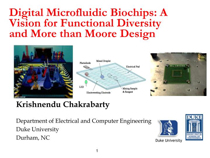
Digital Microfluidic Biochips: A Vision for Functional Diversity and More than Moore Design. Krishnendu Chakrabarty Department of Electrical and Computer Engineering Duke University Durham, NC. Acknowledgments.

E N D
Digital Microfluidic Biochips: A Vision for Functional Diversity and More than Moore Design Krishnendu Chakrabarty Department of Electrical and Computer Engineering Duke University Durham, NC 1
Acknowledgments • Students: Tianhao Zhang, Fei Su, William Hwang, Phil Paik, Tao Xu, Vijay Srinivasan, Yang Zhao • Post-docs and collaborators: Dr. Vamsee Pamula, Dr. Michael Pollock, Prof. Richard Fair, Dr. Jun Zeng (Coventor, HP) • Dr. S. (Krish) Krishnamoorthy, Baxter Healthcare Corporation • Duke University’s Microfluidics Research Lab (http://www.ee.duke.edu/research/microfluidics/) • Advanced Liquid Logic (http://www.liquid-logic.com/): Start-up company spun out off Duke University’s microfluidics research project 2
Talk Outline • Motivation • Technology Overview • Microarrays • Continuous-flow microfluidics: channel-based biochips • “Digital” microfluidics: droplet-based biochips • Design Automation Methods • Synthesis and module placement • Droplet Routing • Pin-Constrained Design • Testing and Reconfiguration • Conclusions 3
Predict the Future Slide adapted from Rob Rutenbar’s ASP-DAC 2007 talk 4
Motivation for Biochips • Clinical diagnostics, e.g., healthcare for premature infants, point-of-care diagnosis of diseases • “Bio-smoke alarm”: environmental monitoring • Massive parallel DNA analysis, automated drug discovery, protein crystallization CLINICAL DIAGNOSTIC APPLICATION Lab-on-a-chip for CLINICAL DIAGNOSTICS Shrink MicrofluidicLab-on-a-Chip 20nl sample Higher throughput, minimal human intervention, smaller sample/reagent consumption, higher sensitivity, increased productivity Conventional Biochemical Analyzer 5
Tubes to Chips: Integrated Circuits • Driven by Information Processing needs IBM Power 5 IC (2004) IBM 701 calculator (1952) 6
Tubes to Chips: BioChips • Driven by biomolecular analysis needs Agilent DNA analysis Lab on a Chip (1997) Test tube analysis 7
Why Do We Care? System Driver for Beyond 2009: “Medical” Intel Research Day 2007: Biochip prototype demonstrated for point-of-care diagnostics and lab testing 2007 10
What are the main types of biochips? Passive (array): all liquid handling functions are performed by the instrument. The disposable is simply a patterned substrate. Active (lab-on-chip, m-TAS): some active functions are performed by the chip itself. These may include flow control, pumping, separations where necessary, and even detection. 11
A T G G C C G T G C C A A C T A T G A G G T A T A A T G T C A C C G T G C T T T A A substrate A C G substrate Microarrays • DNA (or protein) microarray: piece of glass, plastic or silicon substrate • Pieces of DNA (or antibodies) are affixed on a microscopic array • Affixed DNA (or antibodies) are known as probes • Only implement hybridization reaction Hybridized array DNA Sample Optical Scan Unhybridized array Laser 12
Automation Automation Automation Integration Integration Integration Miniaturization Miniaturization Miniaturization Motivation for Microfluidics Test tubes Robotics Microfluidics 13
Control electronics (shown) are suitable for handheld or benchtop applications Biosensors: Optical: SPR, Fluorescence etc. Electrochemical: Amperometric, Potentiometric etc. Printed circuit board lab-on-a-chip – inexpensive and readily manufacturable Microfluidics • Continuous-flow lab-on-chip: Permanently etched microchannels, micropumps and microvalves • Digital microfluidic lab-on-chip: Manipulation of liquids as discrete droplets Multiplexing (Duke University) Mixing: Static, Diffusion Limited 14
Electrowetting • Novel microfluidic platform invented at Duke University • Droplet actuation is achieved through an effect called electrowetting • Electrical modulation of the solid-liquid interfacial tension No Potential A droplet on a hydrophobic surface originally has a large contact angle. Applied Potential The droplet’s surface energy increases, which results in a reduced contact angle. The droplet now wets the surface. 15
What is Digital Microfluidics? • Discretizing the bottom electrode into multiple electrodes, we can achieve lateral droplet movement Droplet Transport (Side View) Note: oil is typically used to fill between the top and bottom plates to prevent evaporation, cross-contamination Pitch ~ 100 μm, Gap ~ 50 μm 16
What is Digital Microfluidics? Transport 25 cm/s flow rates, order of magnitude higher than continuous-flow methods For videos, go to www.ee.duke.edu/research/microfluidics http://www.liquid-logic.com/technology.html 17
What is Digital Microfluidics? Splitting/Merging 18
Demonstrations of Digital Microfluidics Droplet Formation Synchronization of many droplets 19
Advantages • No bulky liquid pumps are required • Electrowetting uses microwatts of power • Can be easily battery powered • Standard low-cost fabrication methods can be used • Continuous-flow systems use expensive lithographic techniques to create channels • Digital microfluidic chips are possible using solely PCB processes Droplet Transport on PCB (Isometric View) 20
Digital Microfluidic Biochip Protein crystallization chip (under development) Capabilities TRANSPORT DISPENSING MIXERS REACTORS DETECTION • Digital microfluidic lab-on-chip • Basic microfluidic functions (transport, splitting, merging, and mixing)have already been demonstrated on a 2-D array • Highly reconfigurable system INTEGRATE 21
Manageable Design Approach • Diverse biotechnology functions major source of requirements for microfluidic architecture • Agent Detection • Precision Dispensing • Enzyme Analysis • Electrochromatography • Capillary Electrophoresis • Molecular/Protein Analysis • Isotachophoretic Separation Biomedical Fluidic Functions: Func.1, Func.2,...…,Func.n Elemental Set of Operations: Op.1, Op.2,.........…,Op.i • Transport • Mixing • Flushing • Filtering • Analysis • Detection • Monitoring • Buffers • Channels • Valves • Mixers Elemental Set of Components Comp. 1, Comp. 2,…,Comp. n • Leverage CAD techniques • Current CAD techniques do not consider unique constraints • Cross-contamination between different bio-molecules • Limited availability of stock solutions for use in assay protocols 23
Design Automation: Biochip Synthesis S1:Plasma, S2: Serum, S3: Urine, S4: Saliva Assay1: Glucose assay, Assay2: Lactate assay, Assay3: Pyruvate assay, Assay4: Glutamate assay S1, S2, S3 and S4 are assayed for Assay1, Assay2, Assay3 and Assay4. • Full-custom bottom-up design Top-down system-level design • Scheduling of operations • Binding to functional resources • Physical design 24
Physical Design: Module Placement • Placement determines the locations of each module on the microfluidic array in order to optimize some design metrics • High dynamic reconfigurability: module placement 3-D packing modified 2-D packing Reduction from 3_D placement to a modified 2-D placement 25
Synthesis Results Bioassay completion time T: 363 seconds Biochip array: 9x9 array 27
Experimental Evaluation (Cont.) • Defect tolerance Bioassay completion time T: 385 seconds (6% increase) 28
Droplet Routing • A key physical design problem for digital microfluidic biochips • Given the results from architectural-level synthesis and module placement: • Determine droplet pathways using the available cells in the microfluidic array; these routes are used to transport droplets between modules, or between modules and fluidic I/O ports (i.e., boundary on-chip reservoirs) • To find droplet routes with minimum lengths • Analogous to the minimization of the total wirelength in VLSI routing • Need to satisfy critical constraints • A set of fluidic constraints • Timing constraints: (the delay for each droplet route does not exceed some maximum value, e.g., 10% of a time-slot used in scheduling) 29
Directly adjacent Diagonally adjacent Static fluidic constraint Dynamic fluidic constraints Fluidic Constraints • Assume two given droplets as Di and Dj, and let Xi(t) and Yi(t) denote the location of Di at time t Rule #1: |Xi(t+1) Xj(t+1)| 2 or |Yi(t+1) Yj(t+1)| 2, i.e., their new locations are not adjacent to each other. How to select the admissible locations at time t +1? Rule #2:|Xi(t+1) Xj(t)| 2 or |Yi(t+1) Yj(t)| 2, i.e., the activated cell for Di cannot be adjacent to Dj. Rule #3:|Xi(t) Xj(t+1)| 2 or |Yi(t) Yj(t+1)| 2. 30
Experimental Verification (a) Experimental verification of Rule #1: droplets begin on electrodes 1 and 4; (b) Electrodes 2 and 3 are activated, and 1 and 4 deactivated; (c) Merged droplet. (a) Experimental verification of Rule #2: droplets begin on electrodes 2 and 4; (b) Electrodes 1 and 3 are activated, and 2 and 4 deactivated. 31
Experimental Verification (Cont.) (a) Experimental verification of Rule #3: droplets begin on electrodes 4 and 7; (b) Electrodes 3 and 6 are activated, and 4 and 7 deactivated; (c) Merged droplet. • To demonstrate that adherence to Rule #1 is not sufficient to prevent merging. Both Rule #2 and Rule #3 must also be satisfied during droplet routing. • These rules are not only used for rule checking, but they can also provide guidelines to modify droplet motion (e.g., force some droplets to remain stationary in a time-slot) to avoid constraint violation if necessary 32
Design of Pin-Constrained Biochips Direct Addressing • Each electrode connected to an independent pin • For large arrays (e.g., > 100 x 100 electrodes) • Too many control pins high fabrication cost • Wiring plan not available PCB design: 250 um via hole, 500 um x 500 um electrode Via Holes Wires Nevertheless, we need high-throughput and low cost: DNA sequencing (106 base pairs), Protein crystallization (103 candidate conditions) Disposable, marketability, $1 per chip 33
Floating electrode Broadcast Electrode-Addressing • Observation “Don’t-Cares” in Electrode-Actuation Sequences Electrode control inputs: 3 values “1” –- activated “0” –- deactivated “x” –- can be either “1” or “0” Therefore, activation sequences can be combined by interpreting “x” Example: A droplet routed counterclockwise on a loop of electrodes Corresponding electrode activation sequences 34
Solution Based on Clique Partitioning • Idea • Combining compatible sequences to reduce # of control pins • Clique partitioning based method Electrodes Nodes Electrodes with compatible activation sequences a clique Optimal combination Minimal clique-partitioning 35
Application to a Multiplexed Bioassay A biochip target execution of a multiplexed assay Sequencing graph model of the multiplexed assay • A glucose assay and a lactate assay based on colorimetric enzymatic reactions • 4 pairs of droplets – {S1, R1}, {S1, R2}, {S2, R1}, {S2, R2}, are mixed in the mixer in the middle of the chip, the mixed droplets are routed to the detector for analysis 36
Addressing Results • Chip layout and broadcast- • addressing result for the • multi-functional chip for • Multiplexed assay • PCR assay • 3. Protein dilution assay Total number of control pins: 37 The addition of two assays to the biochip for the multiplexed assay leads to only 13 extra control pins 37
Testing of Digital Microfluidics Biochips Stimuli: Test droplets; Response: Presence/absence of droplets 39
Electrical Detection Mechanism Electrically control and track test stimuli droplets • Minimally invasive • Easy to implement (alleviate the need for external devices) • Fault effect should be unambiguous Periodic square waveform • If there is a droplet, output=1; otherwise, output=0 • Fault-free : there is a droplet between sink electrodes • Faulty: there is no droplet. Capacitive changes reflected in electrical signals (Fluidic domain to electrical domain) 41
Experimental Platform • Understand the impact of certain defects on droplet flow, e.g., for short-circuit between two electrodes • To evaluate the effect of various defects on microfluidic behavior 42
Conclusions • Digital microfluidics offers a viable platform for lab-on-chip for clinical diagnostics and biomolecular recognition • Design automation challenges • Automated synthesis: scheduling, resource binding, module placement; droplet routing; testing and reconfiguration • Bridge between different research communities: bioMEMS, microfluidics, electronics CAD and chip design, biochemistry • Growing interest in the electronics CAD and circuits/systems communities • Special session on biochips at CODES+ISSS’2005 (appeared in CFP now) • Special issue on biochips in IEEE Transactions on CAD (Feb 2006), IEEE Design & Test of Computers (Jan/Feb’07), invited papers in TCAD 2009, TCAS-I 2009 • Workshop on biochips at DATE’06 • Tutorials on digital microfluidic lab-on-chip at DATE’07, ISCAS’08, ISCAS’09, VDAT 2007; embedded tutorials at VLSI Design’05, ISPD’08 • Other notable activities in digital microfluidics: University of California at Los Angeles, University of Toronto, Drexel University, IMEC (Belgium), Freiburg (Germany), Philips (Netherlands), Fraunhofer Institute (Berlin, Germany), National Taiwan Univ., Tech. Univ. Denmark, Univ. Texas, and many more…. 43