Download
1 / 25
370 likes | 635 Views
O-Ring. MSC.Marc 2005r2 MSC.Patran 2005r2. Estimated Time for Completion: 30 minutes Experience Level: Lower. Topics Covered. Creating rigid and deformable contact boundary conditions Using axisymmetric elements Using Ogden material model Transforming geometries

E N D
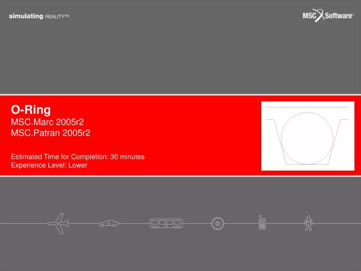
O-Ring MSC.Marc 2005r2 MSC.Patran 2005r2 Estimated Time for Completion: 30 minutes Experience Level: Lower
Topics Covered • Creating rigid and deformable contact boundary conditions • Using axisymmetric elements • Using Ogden material model • Transforming geometries • Associating finite elements to geometries • Modifying analysis output requests • Plotting and graphing the results
Problem Description Hatch O-ring Contact pressure must be sufficiently large to prevent leakage. Submarine’s entrance • In many applications, a contact between two parts are very critical. For example, the contact pressure between an O-ring and a hatch for a submarine need to be sufficiently large to prevent leakage. The groove and the O-ring need to be designed to provide the specified contact pressure. The ring also needs to survive the maximum loading condition.
Problem Description Hatch A Groove r A R O-ring Ring radius, R = 10” Cross section radius, r = 0.25” Section A-A • In this example problem, the analysis of a 3D model of O-ring is simplified using a 2D model. The ring is compressed by the hatch into the groove. An Ogden rubber model is used to model the ring. The hatch and the groove are assumed rigid. • We will use Patran to complete the problem description from a given 2D meshed model and analyze it by using Marc.
Summary of Model Groove Rigid contact Hatch Rigid contact With specified motion <-0.12,0,0> 0.25” O-ring Deformable contact Ogden material model with 3 terms Bulk Modulus is 1.45E9 psi. 10” y x [0,0,0]
Goal • We will determine the contact pressure between an O-ring and a hatch at the closed position. • Minimum principal (maximum compressive) stresses will also be investigated to provide information about the survival of the ring.
Expected Results Contact stresses Max contact stress (pressure) is 6.95 psi.
Expected Results Minimum principal stresses Max compressive stress is 6.98 psi
Create Database a b c d e • Click File menu / Select New • In File Name enter oring.db • Click OK • Select Analysis Code to be MSC. Marc • Click OK
Import Model a b c d Working plane to be used with axisymmetric analysis y y x [0,0,0] x z A given model • Click File menu / Select Import • Select Source to be MSC. Patran DB • Locate and select file oring_model.db • Click Apply Notes: The coordinate of a given model is not correct for axisymmetric analysis. The model needs to be transformed.
Transform Model m d a b c l e g h i j k f Transform geometries to the correct coordinate for axisymmetric analysis • Click Geometry icon • Select Action to be Transform • Select Object to be Curve • Select Method to be Rotate • In Rotation Angle, enter -90 • Check Delete Original Curves • In Curve List, enter Curve 1 2(or select Groove and Hatch) • Click Apply (Click Yes when asked to delete the original curves) • Select Method to be Translate • In Direction Vector, enter <0 10 0> • Check Delete Original Curves • In Curve List, enter Curve 3 4 (or selected Groove and Hatch) • Click Apply (Click Yes when asked to delete the original curves) Notes: When transforming geometries, the checkbox for Delete Original Entities should be checked. Otherwise, the entities will be duplicated. The numbering of the new entities will be different from the original ones.
Transform Model a b c d e f g h i This will keep the ELEMENT numbers of the transformed elements to start from 1. The NODE numbers of the transformed nodes, however, start after the last node number of the original node set. Transforming elements automatically transform nodes attached to the elements being transformed. Transform elements to the correct coordinate for axisymmetric analysis • Click Elements icon • Select Action to be Transform • Select Object to be Element • Select Method to be Translate • In Numbering Option, Starting ID(s), enter 1 • In Direction Vector, enter <0 10 0> • Check Delete Original Elements • In Element List, enter Elm 1:667(or select all elements) • Click Apply
Create Deformable Contact a b c d e f g h i j k l m • Click Loads/BCs icon • Select Action to be Create • Select Object to be Contact • Select Type to be Element Uniform • Select Option to be Deformable Body • In New Set Name,enter oring_contact • Select Target Element Type to be 2D • Click Select Application Region • Select Geometry Filter to be FEM • Select all elements on screen or enterElm 1:667 • Click Add • Click OK • Click Apply Select all elements on screen by drawing a rectangle to include all elements of the ring
Create Rigid Contacts a b c d e f g h i j k l • Select Option to be Rigid Body • In New Set Name,enter groove_contact • Select Target Element Type to be 1D • Click Input Data • Check Flip Contact Side • Click OK • Select Application Region • Select Geometry Filter to be Geometry • Select Groove on screen or enter Curve 6 • Click Add • Click OK • Click Apply
Create Rigid Contacts a b c d e f g h i • In New Set Name,enter hatch_contact • Click Input Data • In Velocity, enter <-0.12,0,0> • Click OK • Select Application Region • Select Hatch on screen or enter Curve 5 • Click Add • Click OK • Click Apply Notes: Make sure the contact sides are correct as shown in Summary of Model.
Define Material a b c d e f g h i • Click Materials icon • In Material Name,enter rubber • Click Input Properties • Select Constitutive Model to be Hyperelastic • Select Model to be Ogden • Select Number of Terms to be 3 • Enter values in Property Name as shown • Click OK • Click Apply
Define Element Properties a b c d e f g h i j k l Quad Element selection tool • Click Properties icon • Select Type to be 2D Solid • In Property Set Name, enter oring_prop • Select Options to be Axisymmetric • Click Input Properties • Click Material icon and select rubber • Click OK • Click Select Members textbox so that Selection Tool appears • Click Quad Element icon • In Select Members select all elements on screen or enter Elm 1:667 • Click Add • Click Apply
Create Load Step o n a b c d e f g h i j k l m • Click Analysis icon • Click Load Step Creation • In Load Step Name, enter close_gap • Click Solution Parameters • Click Load Increment Params • In Total Time, enter 1.0 • Click OK • Click OK • Click Output Requests • Click Select Nodal Results • Click Contact Normal Stress, Contact Normal Force, and Contact Status • Click OK • Click OK • Click Apply • Click Cancel This is to make sure that the Hatch is moved to the specified position since the contact motion was specified by velocity.
Run Analysis and Read Results a b c d e f g h i Select load step • Click Load Step Selection • In Step Select, select close_gap and unselect Default Static Step • Click OK • Click Apply ** Wait until analysis is completed ** Read results file • Select Action to be Read Results • Click Select Results File • Locate file oring.t16 • Click OK • Click Apply
Plot Contact Stresses a b c d e f • Click Results icon • In Select Result Cases, select the last increment • In Select Fringe Result, select Stress, Contact Normal • Select Quantity to be X Component • In Select Deformation Result, select Displacement, Translation • Click Apply Max contact stress (pressure) is 6.95 psi. Maximum contact stress is 6.95 psi
Graph Contact Stresses Along the Surface of the Ring a b c d e f g h i Create a curve to represent a surface of the ring This curve will be used for the purpose of plotting • Click Geometry icon • Select Action to be Create • Select Object to be Curve • Select Method to be 2DArcAngles • In Radius, enter 0.25 • In Start Angle, enter -90 • In End Angle, enter 270 • In Center Point List, enter [0,10,0] • Click Apply Use “Ctrl” button to select nodes on the ring’s surface.
Graph Contact Stresses Along the Surface of the Ring a b c d e f g Associate nodes to the curve • Click Elements icon • Select Action to be Associate • Select Object to be Node • Select Method to be Curve • In Select Nodes, select all nodes along the boundary of the ring • In Select a Curve, select the curve on the ring surface or enter Curve 7 • Click Apply Select nodes on screen Notes: Hold “Ctrl” button once and click on screen to activate the use of polygon selection tool. Double click to finalize the selection. Use View Corners zoom to zoom in for easier selection.
Graph Contact Stresses Along the Surface of the Ring a b c d e f g h i j k l • Click Results icon • Select Object to be Graph • In Select Result Case, select last increment • In Select Y Result, select Stress, Contact Normal • Select Quantity to be X Component • Select X to be Path Length • Click Target Entities icon • Select Target Entity to be Path • Select Addtl. Display Control to be Curves • In Select Path Curves, select curve on the ring from screen or enter Curve 7 • In Point Per Segment, enter 100 • Click Apply
Plot Minimum Principal Stresses a b c d e f • Select Object to be Quick Plot • In Select Result Case, select last increment • In Select Fringe Result, select Stress, Global • Select Quantity to be Min Principal • In Select Deformation Result, select Displacement Translation • Click Apply Max compressive stress is 6.98 psi.
Further Analysis (Optional) • Change the groove angle and investigate how the maximum stress and contact pressure change • Redefine element properties using Hybrid (Herrmann formulation) • Turn on local Adaptive Meshing option in Job Parameters to improve the accuracy of the solutions