Download
1 / 5
50 likes | 156 Views
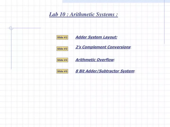
Lab 10 : Arithmetic Systems :. Adder System Layout:. Slide #2. 2’s Complement Conversions :. Slide #3. Arithmetic Overflow :. Slide #4. 8 Bit Adder/Subtractor System :. Slide #5. Carry Out of 1. Carry Out of 0. Carry Out of 1. 3. 0. 0.

E N D
Lab 10 : Arithmetic Systems : Adder System Layout: Slide #2 2’s Complement Conversions: Slide #3 Arithmetic Overflow: Slide #4 8 Bit Adder/Subtractor System: Slide #5
Carry Out of 1 Carry Out of 0 Carry Out of 1 3 0 0 Add the 2 LSB’s. 1+1=10 (2 in binary)…or… 1+1 = 0 and a carry out of 1. Add Carry In + 1 + 0 = 10 Add Carry In + 0 + 0 = 00 Add Carry In + 0 + 0 = 01 1 1 + 1 0 0 0 1 0 0 Ignore the Carry Out A A A A Answer = 4 Cout Cout Cout Cout Cin Cin Cin Cin S S S S B B B B A+B+Cin Cin must be connected to Cout A+B+Cin Cin must be connected to Cout A+B+Cin Cin must be connected to Cout 0 0 0 0 1 0 1 1 1 3 A+B+Cin = S & Cout 1+1+0 = 0 and 1 A+B+Cin = S & Cout 1+0+1 = 0 and 1 A+B+Cin = S & Cout 0+0+1 = 1 and 0 0 0 1 1 0 1 0 0 Full Adder Answer =4 (0100) Lab 10 : Adder system Layout : To demonstrate the process used by a digital adder system, two binary numbers will be added by hand. 0 1 1 Add 3 + 1 using four bit hand addition: 1 0 0 Adder systems are made up of modules called Full Adders. A + B + Cin (carry in) = S (sum) & Cout (carry out). A 4 bit adder requires 4Full Adder modules. Add 3 + 1 using the adder system : Slide #2
Sign Bit Sign Bit 64 64 32 32 16 16 8 8 4 4 2 2 1 1 1 0 0 0 1 1 1 0 1 0 1 1 0 1 0 1 1 1 1 0 0 0 0 0 1 0 0 1 1 1 1 1 0 0 0 1 0 0 1 0 0 0 1 1 0 1 0 1 0 1 0 0 0 0 0 1 + 1 +22 + -22 1 Answer = 0 Lab 10: 2’s Complement Conversion : Signed numbers encoded using 2’s complement notation can be added and subtracted using one process: “The process of addition”. Converting numbers to 2’s complement form is easy. Positive Numbers:Example:Convert +22 into 8 bit 2’s complement form.Rule :2’s complement notation = Binary Notation. 0 0 0 1 0 1 1 0 Process: Write 22 as a 7 bit number. Make the Sign Bit =0 to denote a positive number and your done! 0+ 0+ 16+ 0+ 4+ 2 + 0 = 22 Thus +22 = 00010110 in 8 bit 2’s complement notation. Negative Numbers:Example:Convert -22 into 8 bit 2’s complement form.Rule :2’s complement notationis NOT=Binary Notation. You must use a 3 step procedure to convert the negative number. Step 1: Write –22 as an 8 bit positive numberFrom the work above: +22 = 00010110 Step 2: Invert all bitsThe result of this process is called 1’s complement notation. Step 3: Add 1 to this new binary pattern Thus -22 = 11101010 in 8 bit 2’s complement notation. Theory:Adding a positive and a negative 2’s comp. number will subtract the 2 numbers. Test the Theory: Try22+(-22) At first glance it does not appear to work. The 1 in the MSB is actually a carry out and can be ignored! Slide #3
Overflow from 2 positive numbers always wraps around to the negative end of the number line. In our example 9 + 8 = -15. -15 Answer always falls in the middle NO overflow! (-9)+(-8) 8+9 +15 -16 -14 -12 -10 -8 -6 -4 -2 0 +2 +4 +6 +8 +10 +12 +15 16 (24) –ve #s. 16 (24) +ve #s. Sign Bit 8 4 2 1 9 + 0 1 0 1 0 1 0 0 0 0 0 0 1 1 0 1 0 0 0 1 Negative # 8 0 1 1 1 0 Invert + 1 Add 1 0 1 1 1 1 15 Lab 10: Arithmetic Overflow : Arithmetic Overflow is an error that occurs when 2 numbers being added together generate an answer that requires more bits than are available for the answer. Overflow from 2 negative numbers always wraps around to the positive end of the number line. For example (–9) + (-8) = +15. 5 bit signed numbers will be used to demonstrate arithmetic overflow. The valid range of 5 bit numbers is –16 to +15. The range can be represented using a number line. One number on this side One number on this side Add 9+8. Each number on there own is a valid 5 bit number but there sum (17) exceeds the valid range. The sum turns out to be a negative number. To check which negative number it is: invert and +1 and it will convert to its equivalent +ve number. If the error goes undetected then the system would calculate 9+8 = -15Error! Detecting Arithmetic Overflow errors is easy. All calculators and computers do it. Overflow never occurs if the 2 numbers being added have opposite sign bits. Think about it using the number line. One number on the positive side and the other on the negative side always generates a sum in between Overflowmay occur if the 2 numbers being added have the same sign bits. Think about it using the number line. Both numbers from the positive side may generate a sum that exceeds +15. Both numbers from the negative side may generate a sum that exceeds -16. An overflow detection system checks the logic level of each number’s sign bit. If they are the same then it checks the sign bit of the answer. If the sign bit of the answer is different than the sign bit of each number then overflow has occurred and the system generates an error message. Slide #4
Sign Bit 64 32 16 8 4 2 1 Put the system in the SUB mode. ADD/SUB =1. The XOR gates are controlled inverters and will pass the inverse of the number –4 to the adders. This will make the system subtract 12-(-4). Put the system in the ADD mode. ADD/SUB =0. The XOR gates are controlled inverters and will pass the number –4 to the adders. +12 +4 1 1 0 0 1 0 0 1 1 0 0 1 1 0 0 1 0 1 1 0 0 0 1 1 1 1 1 1 1 0 1 0 1 1 1 1 0 0 1 0 0 0 1 0 0 0 0 0 Invert Add 1 1 1 1 1 1 1 1 0 1 C0 C0 C0 C0 Register B Register B + + Register A Register A 1 1 C4 C4 C4 C4 1 1 Register B 0 0 0 1 1 1 0 0 0 1 0 1 1 0 1 0 0 1 0 0 0 0 0 1 1 0 0 0 1 0 0 0 0 0 0 0 Register B 0 1 0 0 1 0 1 0 0 0 0 0 + Register A + Register A 0 1 0 1 1 1 1 1 1 1 0 0 0 0 1 1 0 0 0 0 1 1 0 1 1 0 0 0 0 1 1 0 0 1 0 0 0 0 0 0 0 0 0 0 0 0 1 0 0 Answer is 8 [12+(-4)] Answer is 16 [12-(-4)] Lab 10: 8 Bit Adder/Subtractor : Two 4-bit adders are combined with XOR gates to create an 8-bit adder/subtractor system. The system will be used to add 12 + (-4) and then subtract 12 – (-4). Load the data registers with the 2 numbers: +12 and –4. Add the numbers and show the response at the S output of the adders. Add the numbers and show the response at the S output of the adders. -4 0 +12 Slide #5