Download
1 / 77
770 likes | 877 Views
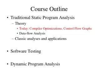
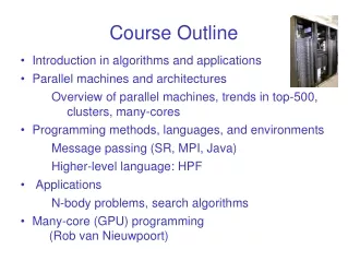
Course outline. CMOS Complementary Metal-Oxide Semiconductor. Introduction. Electronic pathway. Seoul subway. Pyrimidine pathway. From DNA to pathways. Biological information. Two Types of Biological Information The genome , digital information Environmental , analog information.

E N D
CMOS • Complementary Metal-Oxide Semiconductor
Biological information Two Types of Biological Information • The genome, digital information • Environmental, analog information
Genome information Two types of digital genome information • Genes, the molecular machines of life • Gene regulatory networks, specify the behavior of the genes
What is systems biology? Biological System DNA RNA Biomodules Cells Networks Proteins
Programming cell communities Diffusing signal E. coli proteins
Programming cell communities Program cells to perform various tasks using • Intra-cellular circuits Digital & analog components • Inter-cellular communication Control outgoing signals, process incoming signals
Programmed cell applications • Biomedical • combinatorial gene regulation with few inputs; tissue engineering • Environmental sensing and effecting • recognize and respond to complex environmental conditions • Engineered crops • toggle switches control expression of growth hormones, pesticides • Cellular-scale fabrication • cellular robots that manufacture complex scaffolds
Programmed cell applications Pattern formation
Programmed cell applications Analyte source detection analyte source reporter rings
Logic circuit based on inverters • Proteins are the wires/signals • Promoter + decay implement the gates • NANDgate is a universal logic element: • any (finite) digital circuit can be built!
NAND and NOT gate X XY Y X X
Logic circuit based on inverters X R1 X = Z R1 Z gene Y R1 Y gene NAND NOT gene
Why digital? • We know how to program with it • Signal restoration + modularity = robust complex circuits • Cells do it • Phage λ cI repressor: Lysis or Lysogeny?[Ptashne, A Genetic Switch, 1992] • Circuit simulation of phage λ[McAdams & Shapiro, Science, 1995] • Also working on combining analog &digital circuitry
BioCircuit CAD SPICE http://bwrc.eecs.berkeley.edu/classes/icbook/SPICE/
BioCircuit CAD intercellular steady state dynamics BioSPICE a prototype biocircuit CAD tool • simulates protein and chemical concentrations • intracellular circuits, intercellular communication • single cells, small cell aggregates
Genetic circuit elements translation RBS RBS input mRNA output mRNA ribosome ribosome transcription operator promoter RNAp
Modeling a biochemical inverter input repressor promoter output
A BioSPICE inverter simulation input repressor promoter output
Smallest memory: RS-latch flip-flop 0 1 1 0 1 0 1 0 • The output a of the R-S latch can be set to 1 by momentarily setting S to 0 while keeping R at 1. • When S is set back to 1 the output a stays at 1. • Conversely, the output a can be set to 0 by keeping S at 1 and momentarily setting R to 0. • When R is set back to 1, the output a stays at 0.
RS-latch flip-flop truth table R S Q ~Q (n+ 1 ) (n+ 1 ) 0 0 Q ~Q Q = R + ~Q (n) (n) 0 1 1 0 1 0 0 1 ~Q = S + Q 1 1 0 0
Proof of Concept in BioSPICE RS-Latch (“flip-flop”) Ring oscillator _ [R] They work in vivo • Flip-flop [Gardner & Collins, 2000] • Ring oscillator [Elowitz & Leibler, 2000] However, cells are very complex environments • Current modeling techniques poorly predict behavior [A] _ R _ [S] A [B] time (x100 sec) [B] _ S B [C] [A] time (x100 sec) time (x100 sec) Work in BioSPICE simulations [Weiss, Homsy, Nagpal, 1998]
The IMPLIES gate • Inducers that inactivate repressors: • IPTG (Isopropylthio-ß-galactoside) Lac repressor • aTc (Anhydrotetracycline) Tet repressor • Use as a logical IMPLIES gate: (NOT R) OR I Repressor Output Inducer
The IMPLIES gate active repressor inactive repressor RNAP inducer transcription no transcription RNAP gene gene promoter promoter operator operator
The toggle switch pIKE = lac/tet pTAK = lac/cIts [Gardner & Collins, 2000]
The toggle switch promoter protein coding sequence [Gardner & Collins, 2000]
The ring oscillator [Elowitz, Leibler 2000]
The ring oscillator The repressilator network. The repressilator is a cyclic negative-feedback loop composed of three repressor genes and their corresponding promoters, as shown schematically in the centre of the left-hand plasmid. It uses PLlacO1 and PLtetO1, which are strong, tightly repressible promoters containing lac and tet operators, respectively6, as well as PR, the right promoter from phage l (see Methods). The stability of the three repressors is reduced by the presence of destruction tags (denoted `lite'). The compatible reporter plasmid (right) expresses an intermediate-stability GFP variant11 (gfp-aav). In both plasmids, transcriptional units are isolated from neighbouring regions by T1 terminators from the E. coli rrnB operon (black boxes).
Evaluation of the ring oscillator Reliable long-term oscillation doesn’t work yet: • Will matching gates help? • Need to better understand noise • Need better models for circuit design [Elowitz, Leibler 2000]
Evaluation of the ring oscillator Examples of oscillatory behaviour and of negative controls. a±c, Comparison of the repressilator dynamics exhibited by sibling cells. In each case, the fluorescence timecourse of the cell depicted in Fig. 2 is redrawn in red as a reference, and two of its siblings are shown in blue and green. a, Siblings exhibiting post-septation phase delays relative to the reference cell. b, Examples where phase is approximately maintained but amplitude varies significantly after division. c, Examples of reduced period (green) and long delay (blue). d, Two other examples of oscillatory cells from data obtained in different experiments, under conditions similar to those of a±c. There is a large variability in period and amplitude of oscillations. e, f, Examples of negative control experiments. e, Cells containing the repressilator were disrupted by growth in media containing 50mM IPTG. f, Cells containing only the reporter plasmid.
Ring oscillator with mismatched inverters A = original cI/λP(R) B = repressor binding 3X weaker C = transcription 2X stronger
Device physics in steady state “Ideal” inverter Transfer curve • gain (flat,steep,flat) • adequate noise margins “gain” [output] 0 1 [input] • Curve can be achieved with certain dna-binding proteins • Inverters with these properties can be used to build complex circuits
Measuring a transfer curve • Construct a circuit that allows: • Control and observation of input protein levels • Simultaneous observation of resulting output levels inverter CFP YFP R “drive” gene output gene • Also, need to normalize CFP vs YFP