Download
1 / 64
730 likes | 1.06k Views
IE 337: Materials & Manufacturing Processes. Lecture 16: Introduction to Joining. Chapters 30, 31 & 32. Considerations in Joining Joint & Weld Types Joining Processes Brazing and Soldering Processes HW 6 (Due next Tuesday) Multiple Choice Quiz and Problems From Chapters 30, 31 & 32.

E N D
IE 337: Materials & Manufacturing Processes Lecture 16: Introduction to Joining Chapters 30, 31 & 32
Considerations in Joining Joint & Weld Types Joining Processes Brazing and Soldering Processes HW 6 (Due next Tuesday) Multiple Choice Quiz and Problems From Chapters 30, 31 & 32 This Time
A Matter of Scale Space Shuttle Assembly Molecular Motors
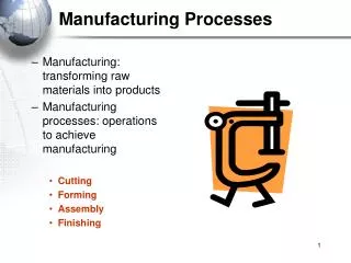
Joining and Assembly Defined Joining - welding, brazing, soldering, and adhesive bonding • These processes form a permanent joint between parts Assembly - mechanical methods (usually) of fastening parts together • Some of these methods allow for easy disassembly, while others do not
Welding Joining process in which two (or more) parts are coalesced at their contacting surfaces by application of heat and/or pressure • Many welding processes are accomplished by heat alone, with no pressure applied • Others by a combination of heat and pressure • Still others by pressure alone with no external heat • In some welding processes a filler material is added to facilitate coalescence
Most welding operations are performed manually and are expensive in terms of labor cost Most welding processes utilize high energy and are inherently dangerous Welded joints do not allow for convenient disassembly Welded joints can have quality defects that are difficult to detect Warping Cracking Cavities / Porosity Inclusions Incomplete fusion Unacceptable contour Provides a permanent joint Welded components become a single entity Usually the most economical way to join components in terms of material usage and fabrication costs Mechanical fastening usually requires additional hardware components (e.g., screws and nuts) and geometric alterations of the parts assembled Not restricted to a factory environment Welding can be accomplished "in the field" Welding Pros & Cons
Considerations in Joining • Coalescence Conditions of the Material: • Heat • Pressure • Surface Conditions • Faying surfaces • Atmosphere • Inert versus need for flux • Resulting Joint: • Fusion Zone • Heat Affected Zone • Base Metal (Unaffected Zone)
Heat (Power) Density • Power transferred to work per unit surface area (power density), W/mm2 (Btu/sec‑in2) • If power density is too low, heat is conducted into work, so melting never occurs • High thermal conductivity in the material is a problem • If power density too high, localized temperatures vaporize metal in affected region • There is a practical range of values for heat density within which welding can be performed • Oxyfuel gas welding (OFW) develops large amounts of heat, but power density is relatively low because heat is spread over a large area • Oxyacetylene gas, the hottest of the OFW fuels, burns at a top temperature of around 3500C (6300F) • Arc welding produces high energy over a smaller area • Local temperatures of 5500 to 6600C (10,000 to 12,000F) common
Power Density • Power Density is the power entering a surface divided by the corresponding surface area: where: PD = power density, W/mm2 (Btu/sec‑in2); P = power entering surface, W (Btu/sec); and A = surface area over which energy is entering, mm2 (in2)
Unit Energy for Melting Um is the quantity of heat required to melt a unit volume of metal • Sum of: • Heat to raise temperature of solid metal to melting point • Depends on volumetric specific heat • Heat to transform metal from solid to liquid phase at melting point • Depends on heat of fusion • Depends on melting temperature of material
Heat Available for Welding • Not all of the input energy is used to melt the weld metal. The net heat available for welding (Hw) is: Hw = f1 f2 H Where: f1 = heat transfer efficiency - actual heat received by workpiece divided by total heat generated at source; f2 = melting efficiency - proportion of heat received at work surface used for melting; the rest is conducted into work metal; and H = total heat generated by welding process
AWS Joint & Weld Types • Joint Types: • Butt Joint • Corner Joint • Lap Joint • T-Joint • Edge Joint • Weld Types: • Fillet Welds • Groove Welds • Plug/Slot Welds • Spot Welds • Flange • Surfacing Welds A B C D E
Joining Processes • Welding Processes • Fusion Welding • Oxyfuel • Arc • Resistance • Solid-State Welding • Friction • Diffusion • Ultrasonic
Factors Affecting Weldability • Filler metal • Must be compatible with base metal(s) • In general, elements mixed in liquid state that form a solid solution upon solidification will not cause a problem • Surface conditions • Moisture can result in porosity in fusion zone • Oxides and other solid films on metal surfaces can prevent adequate contact and fusion
Oxyfuel Welding Processes • Heat provided by fuel gas and oxygen • Flame environment affects the junction material, controlled by oxygen to fuel ratio • Carburizing/Reducing Flame • Neutral Flame • Oxydizing Flame • Characteristics: • Low investment cost • Portability • High operator skill
Maximum temperature reached at tip of inner cone Outer envelope spreads out and covers work surfaces to shield from surrounding atmosphere Flame Environment Illustrated Figure 31.22 ‑ The neutral flame from an oxyacetylene torch indicating temperatures achieved
Figure 31.21 ‑ A typical oxyacetylene welding operation (OAW) OFW Process Illustrated
Arc Welding Processes • Heating is accomplished by electric arc • AC current equipment is less expensive to purchase and operate, but generally restricted to ferrous metals • DC current can be used on all metals and is generally noted for better arc control • Highly automatable • Processes: • Shielded Metal Arc Welding • Gas Metal Arc Welding • Gas Tungsten Arc Welding • Flux Cored Arc Welding • Submerged Arc Welding • Others (Plasma, Stud, …)
Arc Welding Illustrated • A pool of molten metal is formed near electrode tip • As electrode is moved along joint, molten weld pool solidifies in its wake Figure 31.1 ‑ The basic configuration and electrical circuit of an arc welding process
Two Basic Types of AW Electrodes • Consumable – consumed during welding process • Source of filler metal in arc welding • Welding rods (also called sticks) are 9 to 18 inches and 3/8 inch or less in diameter and must be changed periodically • Weld wire can be continuously fed from spools with long lengths of wire, avoiding frequent interruptions • Nonconsumable – not consumed during process • Electrode is tungsten, which resists melting • Electrode is gradually depleted during welding (vaporization is principal mechanism) • Any filler metal must be supplied by a separate wire fed into weld pool
Shielded Metal Arc Welding Figure 31.3 Shielded metal arc welding (SMAW).
Gas Metal Arc Welding 31.4 Gas metal arc welding (GMAW).
GMAW Advantages over SMAW • Better arc time because of continuous wire electrode • Sticks must be periodically changed in SMAW • Better use of electrode filler metal than SMAW • End of stick cannot be used in SMAW • Higher deposition rates • Eliminates problem of slag removal • Can be readily automated
Gas Tungsten Arc Welding Figure 31.9 Gas tungsten arc welding.
Advantages / Disadvantages of GTAW Advantages: • High quality welds for suitable applications • No spatter because no filler metal through arc • Little or no post-weld cleaning because no flux Disadvantages: • Generally slower and more costly than consumable electrode AW processes
Arc Welding Safety Issues • Arc gives off UV Light • Eye safety concerns • Fuel combustion fumes, fuel stocks storage • Storage, misconnection concerns • Electrical energy safety • Guarding concerns • Flux has environmental concerns
Resistance Welding Processes • Coalescence is achieved by using heat from the electrical resistance to the flow of current at the faying surfaces • Highly automatable (5 steps in process) • Surface finish issues • Processes: • Resistance Spot Welding • Resistance Seam Welding • Projection Welding • Others (Flash, Upset, Percussion, …)
Resistance Welding Figure 31.12 Resistance welding, showing the components in spot welding, the main process in the RW group.
Advantages / Drawbacks of RW Advantages: • No filler metal required • High production rates possible • Lends itself to mechanization and automation • Lower operator skill level than for arc welding • Good repeatability and reliability Disadvantages: • High initial equipment cost • Limited to lap joints for most RW processes
Resistance Welding Illustrated Figure 31.13 ‑ (a) Spot welding cycle, (b) plot of squeezing force & current in cycle: (1) parts inserted between electrodes (2) electrodes close, force applied (3) current on, force maintained (4) current off or reduced, force maintained (5) electrodes opened, welded assembly removed
Solid-State Welding Processes • Coalescence occurs due to pressure alone, or heat (below Tm) and pressure combined • Processes: • Diffusion Welding • Surfaces held under pressure at elevated temperature, coalescence occurs by solid-state diffusion of atoms • Friction Welding • Coalescence occurs by heat of friction between surfaces • Ultrasonic Welding • Vibrational friction provides heat and moderate pressure completes the coalescence • Others (Forge, Explosion, …)
Diffusion Welding (DFW) SSW process uses heat and pressure, usually in a controlled atmosphere, with sufficient time for diffusion and coalescence to occur • Temperatures 0.5 Tm • Plastic deformation at surfaces is minimal • Primary coalescence mechanism is solid state diffusion • Limitation: time required for diffusion can range from seconds to hours
Microchannel Process Technology 200 µm wide channels • Patterning: • machining (e.g. laser …) • forming (e.g. stamping …) • micromolding channel header • Channels • 200 µm wide; 100 µm deep • 300 µm pitch • Lamina (24” long x 12” wide) • ~1000 µchannels/lamina • 300 µm thickness channels Single Lamina
Microchannel Process Technology • Laminae (24” long x 12” wide) • ~1000 µchannels/lamina • 300 µm thickness • Patterning: • machining (e.g. laser …) • forming (e.g. stamping …) • micromolding 12” Cross-section of Microchannel Array 24” 24” 12” 12” • Device (12” stack) • ~ 1000 laminae • = 1 x 10⁶ reactor µchannels • Bonding: • diffusion bonding • solder paste reflow • laser welding …
Microchannel Process Technology 12” 24” 12” Microchannel Reactor • Laminae (24” long x 12” wide) • ~1000 µchannels/lamina • 300 µm thickness • Device (12” stack) • ~ 1000 laminae • = 1 x 10⁶ reactor µchannels • Interconnect • welding • brazing • tapping • Bonding: • diffusion bonding • solder paste reflow • laser welding … Bank of Microchannel Reactors (9 x 10⁶ microchannels)
Microlamination [Paul et al. 1999, Ehrfeld et al. 2000*] 12” 24” 12” Microchannel Reactor Microlamination of Reactor *W. Ehrfeld, V. Hessel, H. Löwe, Microreactors: New Technology for Modern Chemistry, Wiley-VCH, 2000.
Figure 31.28 ‑ Friction welding (FRW): (1) rotating part, no contact; (2) parts brought into contact to generate friction heat; (3) rotation stopped and axial pressure applied; and (4) weld created Friction Welding Illustrated
Weld Quality Concerned with obtaining an acceptable weld joint that is strong and absent of defects, and the methods of inspecting and testing the joint to assure its quality • Topics: • Residual stresses and distortion • Welding defects • Inspection and testing methods
Residual Stresses and Distortion • Rapid heating and cooling in localized regions during FW result in thermal expansion and contraction that cause residual stresses • These stresses, in turn, cause distortion and warpage • Situation in welding is complicated because: • Heating is very localized • Melting of base metals in these regions • Location of heating and melting is in motion (at least in AW)
Welding Defects • Cracks • Cavities • Solid inclusions • Imperfect shape or unacceptable contour • Incomplete fusion • Miscellaneous defects
Welding Cracks Figure 31.31 Various forms of welding cracks.
Cavities Two defect types, similar to defects found in castings: • Porosity - small voids in weld metal formed by gases entrapped during solidification • Caused by inclusion of atmospheric gases, sulfur in weld metal, or surface contaminants • Shrinkage voids - cavities formed by shrinkage during solidification
Solid Inclusions • Solid inclusions - nonmetallic material entrapped in weld metal • Most common form is slag inclusions generated during AW processes that use flux • Instead of floating to top of weld pool, globules of slag become encased during solidification • Metallic oxides that form during welding of certain metals such as aluminum, which normally has a surface coating of Al2O3
Incomplete Fusion Also known as lack of fusion, it is simply a weld bead in which fusion has not occurred throughout entire cross section of joint Figure 31.32 Several forms of incomplete fusion.
Weld joint should have a certain desired profile to maximize strength and avoid incomplete fusion and lack of penetration Weld Profile Figure 31.33 ‑ (a) Desired weld profile for single V‑groove weld joint
Figure 31.33 ‑ Same joint but with several weld defects: (b) undercut, in which a portion of the base metal part is melted away; (c) underfill, a depression in the weld below the level of the adjacent base metal surface; and (d)overlap, in which the weld metal spills beyond the joint onto the surface of the base part but no fusion occurs Profile Defects