Download

1 / 16
170 likes | 358 Views
Workshop 5.1. Free Vibration Analysis. Workshop 5.1 - Goals. Our goal is to investigate the vibration characteristics of a motor cover manufactured from 18 gage steel. The cover is to be fastened to a device operating at 1000 Hz.

E N D
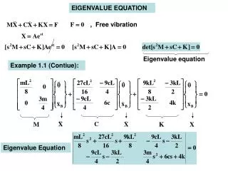
Workshop 5.1 Free Vibration Analysis
Workshop 5.1 - Goals • Our goal is to investigate the vibration characteristics of a motor cover manufactured from 18 gage steel. The cover is to be fastened to a device operating at 1000 Hz. • Specifically, we want to look at the effect of reducing the number of fasteners used in the cover from 5 to 4 for manufacturing efficiency. August 26, 2005 Inventory #002266 WS5.1-2
Workshop 5.1 - Assumptions • The cover is meant to slip over a cylinder and be constrained at the bolt hole locations. To simulate the area contacting the cylinder the surface has been split (see below). We will use a frictionless support on this surface to simulate the contact area. The frictionless support type applies a constraint that is normal to the surface, thus axial and tangential movement is allowed while radial motion is not. • To simulate the bolted connections a fixed support type will be used on the edges of the bolt holes. Split Surface August 26, 2005 Inventory #002266 WS5.1-3
Workshop 5.1 - Start Page • From the launcher start Simulation. • Choose “Geometry > From File . . . “ and browse to the file “Motor_Cover_5.x_t”. • When Workbench Simulation starts, close the Template menu by clicking the ‘X’ in the corner of the window. • Note: Before we begin working with this model we want to bring in the 4 hole version of the part as well. This will allow us to compare results in real time. August 26, 2005 Inventory #002266 WS5.1-4
. . . Workshop 5.1 - Start Page • Before we begin working with this model we want to bring in the 4 hole version of the part as well. This will allow us to compare results in real time. • Highlight the Model branch and “RMB > Duplicate”. • With Model 2 highlighted choose “Geometry > From File . . . “. • Browse to the file “Motor_Cover_4.x_t”. August 26, 2005 Inventory #002266 WS5.1-5
1 Workshop 5.1 - Setup • When the Workbench Simulation GUI opens choose the U.S. inch pound unit system. • “Units > U.S. Customary (in, lbm, psi, F, s) August 26, 2005 Inventory #002266 WS5.1-6
. . . Workshop 5.1 - Setup • The 2 models we have chosen are now contained in separate Model branches (Model and Model 2). To make the comparison more intuitive, rename the model branches by right clicking on each Model branch. Rename as: • Model = “5 Hole Cover” • Model 2 = “4 Hole Cover” August 26, 2005 Inventory #002266 WS5.1-7
Workshop 5.1 - Preprocessing • Since the models consist of surface geometry we will be shell meshing the parts. The first preprocessing task is to specify the thickness for the parts in both branches. • Highlight the “Part 1” branch for the 5 Hole Cover. • Notice the “Thickness” field is currently displayed in yellow to indicate it is undefined. • Left click in the thickness field and set the thickness = 0.05 in. Repeat for 4 Hole Cover. 3 4 August 26, 2005 Inventory #002266 WS5.1-8
Workshop 5.1 - Environment • Highlight the “Environment” branch for the 5 Hole Cover. • Select the split surface, RMB and apply the frictionless support (make sure you are in face select mode). • “Insert > Frictionless Support” Split Surface 5 6 August 26, 2005 Inventory #002266 WS5.1-9
. . . Workshop 5.1 - Environment • Switch to edge select mode. • Hold the control key and select the edges for each hole. • In the graphics window RMB to apply the fixed support. • RMB: “Insert > Fixed Support”. 7 8 August 26, 2005 Inventory #002266 WS5.1-10
Workshop 5.1 – Solution Setup • To determine the natural frequencies for the models we will use the “Frequency Finder” tool. • Highlight the Solution branch and insert the frequency finder. • RMB: “Insert > Frequency Finder” 9 August 26, 2005 Inventory #002266 WS5.1-11
. . . Workshop 5.1 – Solution Setup • IMPORTANT: steps 6 through 9 completes the setup for the environment of the 5 hole cover. Before solving we need to setup the 4 hole cover using the same boundary conditions. • Highlight the Environment branch for the 4 Hole Cover model. • Repeat steps 5 to 9 for the second environment. 10 August 26, 2005 Inventory #002266 WS5.1-12
Workshop 5.1 - Solution • With the branches for each model prepared we are ready to solve. As a final check verify the status symbols next to the branches. All branches should have either: • Lightening bolt (ready) • Green check mark (complete) • Solve both models. • Highlight the “Project” branch and solve both models: • RMB: “Solve” • Note: solving from the Project branch causes all unsolved branches to be solved. Had we wished to solve only one branch we could have highlighted only that branch then solved. August 26, 2005 Inventory #002266 WS5.1-13
Workshop 5.1 - Results • After both solutions are complete expand the Frequency Finder tools for each branch (click the ‘+’ to the left of the branch). • Highlighting individual frequency results will cause a representative plot to be displayed. • The detail for each frequency shows the mode’s frequency. August 26, 2005 Inventory #002266 WS5.1-14
. . . Workshop 5.1 - Results • To get an overall view of the results we can use the worksheet view. Highlight one of the frequency finder branches and click on the Worksheet tab. Repeat for the other FF tool. August 26, 2005 Inventory #002266 WS5.1-15
Workshop 5.1 - Comments • Remember: • Displacements reported in mode shapes do not reflect the actual displacements. Actual displacements will depend on the energy input to the system. August 26, 2005 Inventory #002266 WS5.1-16