Download
1 / 24
240 likes | 300 Views
First topic: Cable integration in 3-D printed model enclosure. “Alternative” view & option for feeding inboard boardstack’s power cable through. As discussed in our meeting today. other HV cables. These are the best contacts I know of (and the contacts are the most crucial feature of course)…

E N D
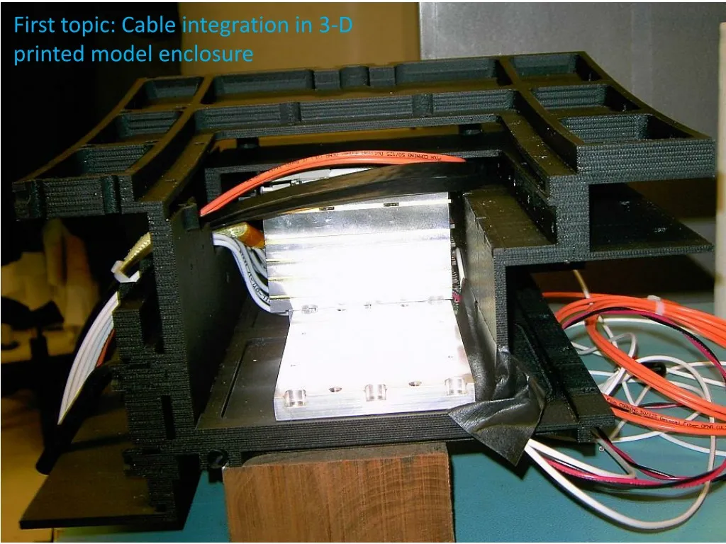
First topic: Cable integration in 3-D printed model enclosure
“Alternative” view & option for feeding inboard boardstack’s power cable through. As discussed in our meeting today. other HV cables
These are the best contacts I know of (and the contacts are the most crucial feature of course)… • Used (equivalent D connector) in STAR, excellent results • Is 11mm height too much? • Plastic dummy in fab now at IU • Received first parts, test assembled.
Making the clock/data cable connection with • Low height • Proper strain relief on cable • Small footprint on SCROD clk/data cable(s), e.g. ultraflat cat 7 ?? connector board locking mezzanine connectors strain relief SCROD • Similar technology was used at IU for STAR SSD • That case was larger (taller) but it can be shorter and smaller with the right cable for iTOP • The solder post terminals seen here were necessary because it was aluminum wire cable, very fragile. We can solder direct to PCB for iTOP • Strain relief block custom fitted to cable shape. (Or can pour epoxy for strain relief.)
Real cable that you can buy from someplace other than amazon.com / no-spec asian import. With a real spec, including a UL approval. VW-1 should be good enough for the short pigtail connections. Anyway we have to deal with it for the power wires too. At worst, in suitable flame-retardant sleeving it should be approvable. I don’t have this yet, so I don’t know about flexibility. But it is probably similar to the “Fosmon” brand cat7 I have, which is pretty nice on flexibility. Termination may be tedious.
IU iTOP cables/power/cooling update 12/22/2014 – also see other slides on cooling G. Visser • Power supplies selection/evaluation • Wiener • ordered one module; ships from factory 12/23, ETA IU week of 1/5 • Andreas Ruben will travel to IU to setup, and discuss requirements etc. • Keysight i.e. HP • Matt shipped 2nd unit here; examined but not powered yet • Excelsys • Cost is such as to merit serious consideration • Will sketch out what I think would be a good design around these, and cost it • Matt has sent 2 Xg3 power modules (the ones we’d use) and 6-slot mainframe (not exactly the one we’d use but close enough for evaluation). • The setup • (Too) Heavy cables found for basic preliminary evaluation of supplies with 0.5V drop restriction • Bought 12AWG cable for test (Belden #5000FE, 2C 12AWG + foil shield) • Sense cable found I think (have to get permission to borrow) • 200VAC power source found, 100VAC also possible (both 60Hz though but should be ok); will start with 208VAC for simplicity
SCROD cables • Have some super-limp flexible wire (1.8m, 16AWG & 20AWG) samples from Jaguar Industries. Also some decent (tougher but less limp) wire from Polar Wire Inc. • Breaking news – just received from Jaguar 1000ft 16AWG white, ordered last Wednesday (see next slide) • Patch connectors • See following slides • External power cables • Urgently need info on cross-section constraints… (Est. <0.44” dia. / boardstack) • Length info is also needed for proper evaluation of the power supplies, almost as critical • Meanwhile have started process for custom combined power & sense cable • Request for design & quote initiated with Alpha Wire • That was the vendor for several very similar cables I did for STAR • Cooling issues • Did get some communication back from EPEC technical contact… (Will discuss). I need to get back to him for more info, but I am not hopeful on a reasonable price. • Ordered 4x4” 2mil indium foil, in stock, maybe have it monday.
For module 01, use colored heatshrink for wire id. Need to order some 20AWG or 18AWG if that must be the plan (tbd…) instead of all 16AWG.
Power wire termination at SCROD • Soldering: adequate wetting of all strands of a large wire like 16AWG is difficult to achieve. Particularly with a fine stranding and in a small space on a high-value PCB assembly. Use of a large amount of flux is not desirable (would need to be cleaned, and that is difficult). • The result can be disconnected strands, unequal stresses when flexing and then broken strands, a hot connection and ultimate failure. • Matt’s soldering of the two “regular stranded” smaller wires on this board (for cal circuit power) also does not achieve adequate wetting through the whole hole/wire. • The better way is to crimp the wire to a pin and then solder the pin to the board. (Or, consider a connector but the latter is probably out of the question.) • Of course, have to identify a pin of the right size and shape, since this is too small a job for custom pins. Fortunately, I think that is done next slide. • Most of the difficult termination work can be done in advance, soldering to the board is a relatively simple final step. • Wire strain relief to the pin is easily achieved with glue-loaded heatshrink– unlike strain relief for direct connection to a PCB hole, I don’t know a good simple plan there apart from making a bracket to tie the wire down someplace else on the board.
3914-0-01-15-00-00-08-0 WRONG SIDE OF BOARD – My Bad!
The pins are cut down on one side (to a flat) for this prototype only, because holes on SCROD are too close together. WRONG SIDE OF BOARD – My Bad!
Only 2 of the 6 power wires are actually soldered to SCROD here • Data/clock cables are not here
It would be good to implement sheet-metal “fake rear wall with cable slot” on the back of this test fixture… Will try.
I believe some changes are necessary in the hole size, solder pad size, locations, and thermal relief for the power connection pads on SCROD production rev. Understood the details will need to be defined soon. The existing SCROD boards will not be compatible with production power (at least) pigtail. But I’m sure we can hack it somehow to enable module 01. Probably best with short lengths of solid copper wire in place of the pins.
Thinnest option I know of • But rather wide… • Mouser has some stock (2 ordered) • Not clear if 16AWG crimp is available, but we do not want solder connection I think. Needs investigation. • Equivalent to Nicomatic 220 series A=34mm 6 contacts
A backup plan – not preferred 10A 23.5mm