Download
1 / 23
240 likes | 402 Views
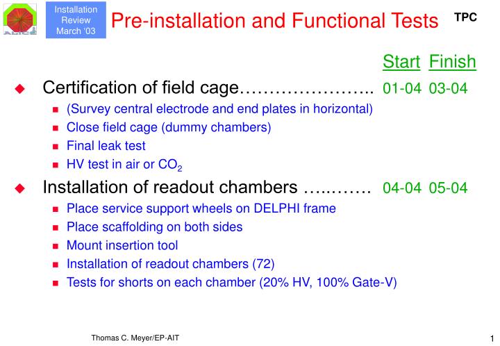
Pre-installation and Functional Tests. Start Finish Certification of field cage………………….. 01-04 03-04 (Survey central electrode and end plates in horizontal) Close field cage (dummy chambers) Final leak test HV test in air or CO 2 Installation of readout chambers …..……. 04-04 05-04

E N D
Pre-installation and Functional Tests StartFinish • Certification of field cage………………….. 01-04 03-04 • (Survey central electrode and end plates in horizontal) • Close field cage (dummy chambers) • Final leak test • HV test in air or CO2 • Installation of readout chambers …..……. 04-04 05-04 • Place service support wheels on DELPHI frame • Place scaffolding on both sides • Mount insertion tool • Installation of readout chambers (72) • Tests for shorts on each chamber (20% HV, 100% Gate-V) Thomas C. Meyer/EP-AIT
Service Support Wheel & ROC Mounting Tool Service Support Wheel ROC End Plate Thomas C. Meyer/EP-AIT
StartFinish Survey of readout chambers……………… 06/04 06/04 Load TPC with dummy ITS Combine with ITS rail deflection test Incline TPC to beam angle 1-2 mbar pressure in TPC Mount “I-bar” on shaft side Survey of chambers on both TPC sides (photogrammetry) Record individual positions of chamber mounting points 3 for IROCs and 4 for OROCs (serve as reference) Pre-installation and Functional Tests Thomas C. Meyer/EP-AIT
StartFinish Trial assembly of TPC in space frame…… 07/04 07/04 Survey and adjustment of TPC-Space Frame rail system Move TPC into space frame and record insertion procedure Check for stability of reference positions Move TPC back into DELPHI frame Pre-installation and Functional Tests Space Frame TPC in DELPHI Frame Thomas C. Meyer/EP-AIT
Pre-installation and Functional Tests StartFinish • Alignment of readout chambers…………… 08/04 08/04 • TPC inclined and compensation (I-) bar mounted • New survey of TPC end plates • Individual machining (shimming) of mounting points • Placement of shims and final survey • Fill TPC with drift gas (Ar-CO2) • Requires that TPC gas system is temporarily installed in SXL2 • Installation of laser calibration system……. 09/04 09/04 • Mount beam telescopes and splitters on end plates • Geometrical adjustments • Tests with He-Ne-lasers Thomas C. Meyer/EP-AIT
Pre-installation and Functional Tests StartFinish • Installation of electronics……………………10/04 01/05 • Install service support wheel and scaffolding • Mount front end- and readout electronics • Mount DCS, LV, cooling and services • Apply LV power (one 20° sector only); monitor temperature • Pulser, grounding and crosstalk tests • Check entire readout chain • HV tests with cosmics and laser (266 nm) • Pre-commissioning of TPC…………………02/05 02/06 • Sector-wise tests with cosmics and laser • Full functionality of readout system • Full functionality of DCS and support systems Thomas C. Meyer/EP-AIT
Pre-installation Schedule Delays prior to or during pre-installation shall be absorbed by the pre-commissioning period Thomas C. Meyer/EP-AIT
StartFinish Transfer of TPC from SXL2 to SX2………………...05-06 05-06 Lift DELPHI frame with TPC out of clean room Load both on a low-bed truck Move to SX2 by truck Unload truck in SX2 Transfer from SX2 to UX25………………………… 05-06 05-06 Crane in SX2 lowers TPC to underground Crane transfer from SX2 to UX25 Connect DELPHI frame to space frame TPC insertion….…………………………………….. 05-06 06-06 Survey of TPC-Space Frame rail system (theodolites!) Slide TPC into space frame General survey & alignment (theodolites) TPC in place and aligned………………………….. June 2006 Installation Procedure Magnet Space Frame TPC in DELPHI Frame Thomas C. Meyer/EP-AIT
Transport To SX2 TPC in DELPHI Frame Thomas C. Meyer/EP-AIT
Lowering Of TPC Through Shaft Thomas C. Meyer/EP-AIT
Insertion In Space Frame Magnet Space Frame Thomas C. Meyer/EP-AIT
StartFinish Preparation for ITS installation…………………….. 06-06 06-06 Installation of extension rails Removal of TPC from interaction point (IP) TPC on stand-by during ITS installation………….. 06-06 10-06 Gas circulation active Install Lasers and beam guides in UX25…………. 06-06 08-06 TPC reinsertion……………………………………… 10-06 11-06 Move TPC back into IP position Survey (theodolites) and inspection for damage Connection of power and services Connection of readout/DCS cables Removal of extension rails TPC installation complete…………………………. Nov/Dec 2006 Installation Procedure Thomas C. Meyer/EP-AIT
Installation Schedule Thomas C. Meyer/EP-AIT
Installation Tools The DELPHI Barrel RICH Frame • Only one (major) tool used: Serves as handling, transport and installation tool.This frame is also used for the assembly of the TPC. Thomas C. Meyer/EP-AIT
Survey and Alignment • TPC and service support wheels sit on sliding (friction) pads • Need CERN survey team in all phases: • Photogrammetry on surface • Traditional methods such as theodolites in cavern • Need fiducial marks (“Taylor balls”) on end plates (6 + 6) • Need identifiers (etiquettes) on service support wheel • Requires perhaps special supports on service support wheel to make identifiers visible through cabling layers. • Should be considered in view of frequent TPC movements • Need lines of sight to Taylor balls • Space frame and rail sag • Space frame sags each time another detector is mounted! • --> do initial TPC survey and then a… • …final survey when space frame is full. Thomas C. Meyer/EP-AIT
CERN Infrastructure Use • Service & Support groups: • EP-TA1 Gas working group • EP-TA2 Construction & assembly, installation assistance, emergency interventions • EP-ED Front endelectronics • EST-LEA Installation & integration Cabling from service support wheels to racks • EST-SU/EXP Survey and alignment (Task Leader: C. Lasseur) • ST-CV Cooling and ventilation systems • TIS Authorization for use of equipment (lasers, field cage HV) • Cranes and special vehicles • Standard hall cranes • One movable crane (35 t) plus driver for one day • Low-bed truck (35 t) for one day and one transport • Distance is only ~100 m from SXL2 to SX2! Thomas C. Meyer/EP-AIT
Commissioning • DCS fully functional to take control of operation • Imperative for all subsequent tasks and functions • Gas mixture and quality • Detector was already filled with drift gas prior to ITS installation • Gas quality (O2 and H2O) checked • If not okay, check for leaks. • Full test of gas system and safety features • Startup of all cooling systems • Electronics, resistor rods, thermal screens • Low voltage • Monitor temperature • Check for shorts • Inspection of grounding and shielding • HV (all systems) • Relies on gas quality • Gradual ramp-up of all supplies and current monitoring Thomas C. Meyer/EP-AIT
Readout system Check for correct cabling Check for oscillations, high pedestals, noise sources Pulse readout electronics Look for cosmic signals (if HV is operational) Laser calibration system Power lasers Send beams to TPC Requires special safety precautions! Beam alignment and correlation Read out tracks with DAQ Do first calibration series with B = 0 Commissioning (cont’d) Thomas C. Meyer/EP-AIT
Field cage & CERN’s host responsibilities Personnel and Resources 2004 2005 2006 2007 EP-AIT 3 3 3 0.25 FC, DCS, Installation EP-TA1 0.5 0 0 0 Gas-WG EP-TA2 18 0 0 Field Cage Constr. 4 0.1 3.5 1 0.2 EP-ED Front End Electr. EST-LEA Install. & Integr. General continuous support EST-SU/EXP Survey 0.6 0.1 0.5 0 ST-CV Cooling TIS Safety 0 0 0.01 0.01 Thomas C. Meyer/EP-AIT
Readout chambers, cooling and services Electronics Laser calibration system Personnel and Resources 2004 2005 2006 2007 Construction Bratislava x x x x Frankfurt 1.5 1.5 1.5 0 Electr., LV, Services,Calibr. Gating, SSW GSI Constr. & Cool. x x 0 x Heidelberg SSW, Constr. PASA Bergen x x x x Heidelberg x x x x ALTRO All systems 0.1 0.1 0.1 0 Copenhagen Thomas C. Meyer/EP-AIT
Risks and Concerns • Technical • Commissioning period is short (but we have extensive pre-commissioning!) • Stability of readout chamber position in view of frequent TPC movements • Regular (yearly) TPC roll-outs for ITS maintenance and repair • Personnel • Possible shortage of manpower • Forecasting of resources difficult • Scheduling • Slippage due to shortage of manpower • Unknown delays from ITS maintenance scenario • Re-commissioning of TPC Thomas C. Meyer/EP-AIT
Maintenance and Access In the Future • Field Cage (low risk item): • The most critical components are the resistor rods • They are exchangeable but require, scaffolding, special handling tools and partial dismounting of electronics. • If failure is on absorber side, TPC must be moved out of IP position, necessitating complete uncabling of the service support wheels. • Un- and recabling of TPC: max. 20 work days (8 h)Repair work and debugging: 10 d • ROCs (low risk item): • The most sensitive components are the wires (breakage and aging) • Same arguments as for the resistor rods • Electronics and DCS: • Standard maintenance at the level of the service support wheels • Requires scaffolding for access • Laser Calibration System: • Standard maintenance at the level of the end plates Thomas C. Meyer/EP-AIT
ITS Trial Assembly Rails TPC ICV Thomas C. Meyer/EP-AIT