Download
1 / 24
240 likes | 328 Views
FIREWATER PUMP P6001A installation. FEB 2006. as reported by Mark Dye. N. East isolation gate. West isolation gate. P6003B. P6003A. P6001A. P6001B. P6002A. P6002B. East firewater pond. West firewater pond. Pump house layout. Unpacking P6001A. This is the pumps hydraulic end.

E N D
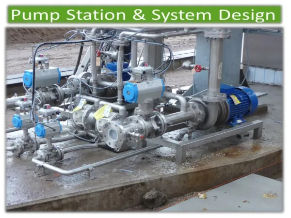
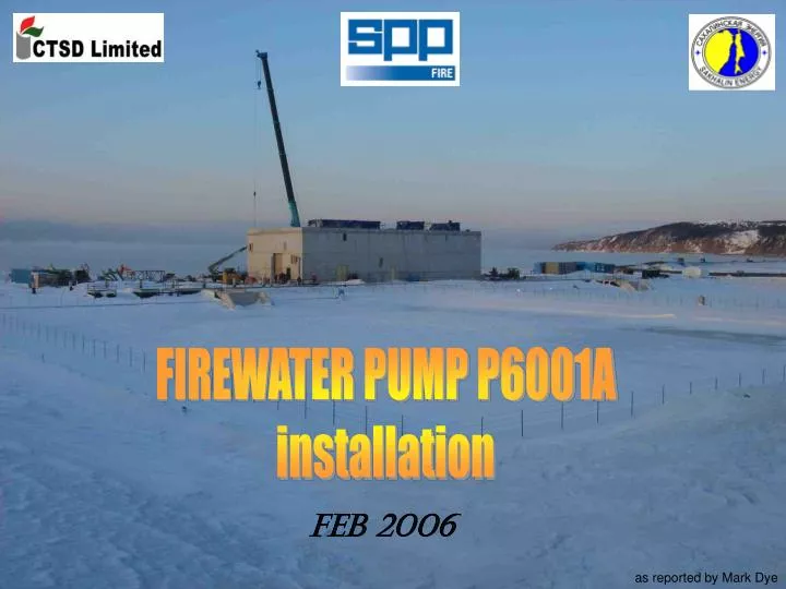
FIREWATER PUMP P6001A installation FEB 2006 as reported by Mark Dye
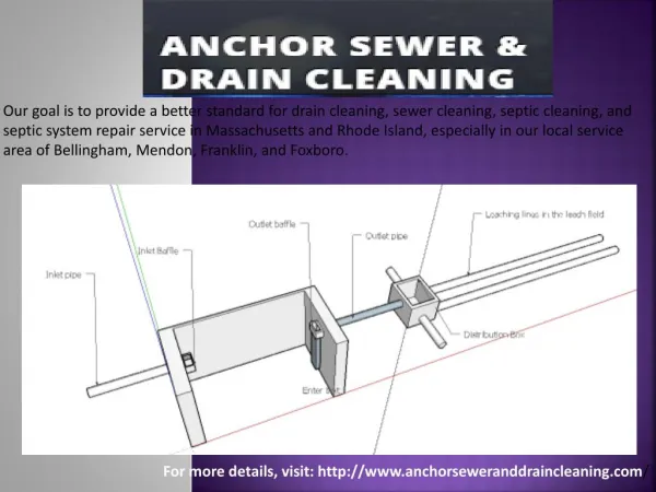
N East isolation gate West isolation gate P6003B P6003A P6001A P6001B P6002A P6002B East firewater pond West firewater pond Pump house layout
This is the pumps hydraulic end With the pump submerged, the water flows up through the shaft housing
A shaft bearing is installed between each pipe spool and clamped between the flanges The bearing is water lubricated and made of PTFE
The shaft joining piece has a left hand thread! The next pipe spool is lowered into position
The flanges are bolted together, The support is opened, and the pump is lowered. then torqued down to 175 ft-lbs.
With all the parts assembled we have… The pump at approx 2.5 metres Three spools at 1.7 metres each One spool at 1 metre Giving a total of 8.6 metres Now we need the stuffing box assembly
The stuffing box assembly is unpacked, And the top bearing assembly removed.
The top bearing assembly is keyed to the shaft because it also contains a ratchet device to prevent back turning of the shaft.
Thread the shaft through and line up the spool bolts. The whole assembly now needs to be lifted to remove the spool support. The combined weight is now 3.7 tonnes.
The coupling housing and motor stand installed. The coolingwater supply, …and return, and constant level oiler is fitted.
PUMP SPECIFICATIONS Pump speed 1480rpm Test pressure 33barg Rated flow 240 l/s (864t/hr) Head 158.4 mtrs. (15 barg)
The jockey pump is exactly the same as the main pumps, …only in miniature!
The pump had it’s first test run… …flushing firemains into the night!