Download
1 / 24
240 likes | 336 Views
Senior Design SD1107 Solar Module Observation Device. Team Leader: Collin Howe , CprE Webmaster: Jacob Rasmuson , CprE Communications: Arthur Fiester , CprE Team Member: Alex Rannow , EE Team Member: Timothy Fox , EE Academic Advisor: D r . Ahmed E. Kamal

E N D
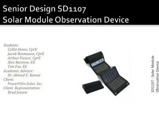
Senior Design SD1107 SolarModule Observation Device SD1107 - Solar Module Obeservation Device Team Leader: Collin Howe, CprE Webmaster: JacobRasmuson, CprE Communications: Arthur Fiester, CprE Team Member: Alex Rannow, EE Team Member: Timothy Fox, EE Academic Advisor: Dr. Ahmed E. Kamal Client: PowerFilm Solar, Inc. Client Representative: Brad Jensen
Agenda • Executive Summary • Project Overview • Modules • Sensing Circuitry • Microcontroller • Android Application • Development • Schedule and Cost SD1107 - Solar Module Obeservation Device
Executive Summary Problem Statement PowerFilm wishes to have a remote measurement device that can communicate with a smartphone application over a Bluetooth interface. Benefits of this device include the following: • Access to information about charging/discharging rates to give the user an in-depth look into the status of the device. • Logging capabilities which will allow users to track the solar module’s efficiency. • Estimated charging times which will allow the user to track the charge progress of the device. • Real-time data which will help determine optimal placement angles to place the solar module. SD1107 - Solar Module Obeservation Device
Requirements • Bluetooth-connected voltmeter/ammeter device, interfaced with solar panel and storage battery. • Smartphone application to receive data and to display battery life and charge time • Device settings must be modifiable by the smartphone application when connected • A 1 in2 footprint PCB • Operating temperature range of -40°C ~ 105°C • Must be able to measure voltages of 0-15.5VDC, and currents 0-0.5A • Powered by solar panel’s storage battery • Multiple power states (Active, Standby, Sleep) • Maximum production cost of $20/unit • Must log data over specified time if so configured by user SD1107 - Solar Module Obeservation Device
Wishes • Smartphone app with graphing capability to display data (zoom) • USB and/or GSM connectivity • User-defined sampling rates (1/2 second – 1 hour intervals) • Smartphone app able to control multiple solar devices • Tabbed user interface SD1107 - Solar Module Obeservation Device
Constraints and Limitations Development • Time • Access to development community • Experience with programming with the microcontroller and Android application Device • Small size of PCB (less 1 in2) • Low power consumption (Must draw no more than 50mA of current in full operation) • Maximum production cost ($20) SD1107 - Solar Module Obeservation Device
Solution • TI MSP430F247 microprocessor with PAN1315 Bluetooth radio connected to sampling circuitry • Integrated Bluetooth antenna inlaid in PCB • Mobile phone application running on a Bluetooth-enabled Android phone • Android application programmed in Java using Eclipse IDE SD1107 - Solar Module Obeservation Device
System Overview SD1107 - Solar Module Obeservation Device
Risk Management • Losing a team member • Unable to utilize Bluetooth • PCB integration • Component damage during fabrication • Design is incorrect and requires rework SD1107 - Solar Module Obeservation Device
Technology/Tradeoffs MSP430+PAN1315 vs. CC2540 vs. Other All-In-One MCU/Radio: • The MSP430 + PAN1315 option is somewhat more expensive than some other options • Much better support community • Complete system and demo/evaluation equipment • Uses universally-accepted Bluetooth2.1+EDR (The CC2540 used newer, backwards-incompatible Low Energy Bluetooth that has yet to be implemented in any end user devices.) Component Antenna vs. PCB Inlaid antenna • Component Antenna provided pre-engineered Bluetooth 2.4GHz antenna • Component antenna adds expense (No extra monetary expense for using PCB Inlaid antenna from TI Designs) • Inlaid PCB Antenna requires relatively large footprint on our PCB SD1107 - Solar Module ObeservationDevice
Sensing Circuitry: Overview Current Sensing: • 20 mΩ sense resistor in series with lines of interest • Voltage drop across resistor fed into 200 V/V differential amplifier • Output of amplifier fed into ADC of microcontroller • Use ratio of 0.25A/V to calculate current Voltage Sensing • Accomplished by voltage divider • Fraction of Vcc inputted into ADC of microcontroller 2.1 V Zener diode placed at ADC for protection SD1107 - Solar Module Obeservation Device
Schematic: Sampling Circuitry SD1107 - Solar Module Obeservation Device
Microcontroller: Overview ADC Interface to the Current/Voltage sensing circuits • 12 bits of resolution • Measure VIA timer interrupt at certain user-defined intervals (1/2 second to 1 hour) • Software scaling to actual voltages/currents Bluetooth Radio Control • Communicate with TI/PAN1315 Bluetooth Radio over UART • Initiate as device using SPP (Serial Port Profile) • Communicate through MindTree/TI Bluetooth Stack VIA RTOS (Free Real Time Operating System, open source) Power States • Able to lower power state of MSP430 into “standby” and “sleep” modes through software/radio control SD1107 - Solar Module Obeservation Device
Microcontroller: Device Concept SD1107 - Solar Module Obeservation Device
Microcontroller: Program Structure SD1107 - Solar Module Obeservation Device
Schematic: Microcontroller and Bluetooth Transceiver To power supply(2V to 3.6V DC) To Current &Voltage sensing circuits SD1107 - Solar Module Obeservation Device LEDs implemented in prototype only
Android Application: Overview • Makes use of Bluetooth on the Android hardware to interface with our device. • Communication over GSM and USB are desirable possibilities as well, but might be unfeasible. • Must be able to alter the configuration of the monitoring device(such as sampling rates and logging options). • Incorporate data from the device into a friendly user interface. SD1107 - Solar Module Obeservation Device
Android Application: GUI Home Screen • Display current status of tethered devices and provide quick access to them. • Allow access to application wide variables Device Screen • Controls power state and pinging function • Displays up-to-date voltages and currents along with a graph of previous data • Allows user to set device settings SD1107 - Solar Module ObeservationDevice
Android Program Structure SD1107 - Solar Module Obeservation Device
Testing Module Testing: Determine if each module is working independently.(Test voltage/current for correct output based on controlled input. Test Android application against previously-implemented SPP terminal device) Integration Testing: Once it is determined that each module is working within respective parameters we will integrate all three modules in a lab environment System testing: Finally the system test will involve system integration between our working device and a testbedsolar panel in “real world” conditions. SD1107 - Solar Module ObeservationDevice
Testing SD1107 - Solar Module ObeservationDevice
Schedule Completed Tasks • Project plan & design document • Technology Selection • Detailed Design including all schematics • Acquired components and development tools • Tested and verified the sampling circuitry • Android Application development Remaining Schedule • Module development and testing • Establish Bluetooth connectivity • Integrate sampling circuitry with microprocessor • End product testing and debugging SD1107 - Solar Module ObeservationDevice
Cost Estimation SD1107 - Solar Module Obeservation Device
Questions? 01010001 01110101 01100101 01110011 01110100 01101001 01101111 01101110 01110011 00001101 00001010 ? SD1107 - Solar Module Obeservation Device