Download
1 / 60
670 likes | 939 Views
Introducing the Specifications of the MEF. An Overview of MEF 6.1, 10.2, 10.2.1 Carrier Ethernet Definitions and Attributes 2011 December. Agenda. Approved MEF Specifications This Presentation About this Specification Terminology, Concepts Section Review Major topics Minor topics

E N D
Introducing the Specifications of the MEF An Overview of MEF 6.1, 10.2, 10.2.1 Carrier Ethernet Definitions and Attributes 2011 December
Agenda • Approved MEF Specifications • This Presentation • About this Specification • Terminology, Concepts • Section Review • Major topics • Minor topics • Examples/Use Cases • Summary
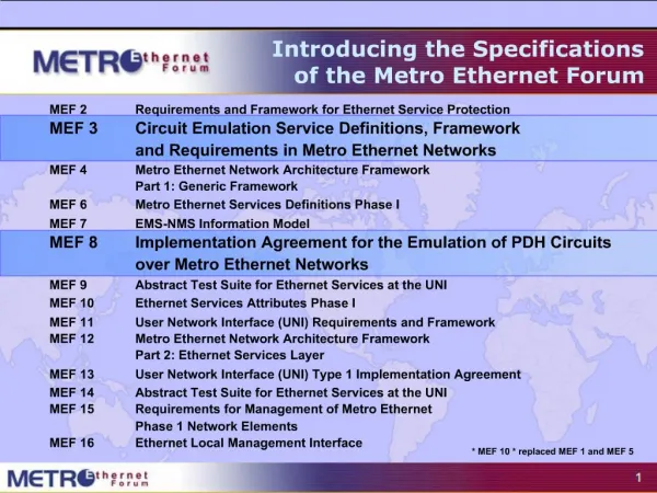
Approved MEF Specifications * MEF 6.1 replaced MEF 6., MEF 7.1 replaced MEF 7, MEF 10.2.1 & MEF 10 .2 replaced MEF 10.1.1, MEF 10.1, MEF 10 which replaced MEF 1 and MEF 5.
This Presentation • Purpose: • This presentation is an introduction to MEF 6, MEF 10.2 and MEF 10.2.1 which highlights key recommendations and requirements in these specifications as well as the Metro Ethernet Network Architecture concepts further defined in MEF 4. • Audience • Equipment Manufacturers building devices that will carry Carrier Ethernet Services. • Useful for Service Providers architecting their systems • Other Documents • Presentations of the other specifications and an overview of all specifications is available on the MEF web site • Other materials such as white papers and case studies are also available
Key Carrier Ethernet Definitions and Concepts Provides foundational definitions and concepts for Metro Ethernet Services, service attributes and parameter requirements and as well as traffic classification, traffic profiles and related recommendations to deliver Carrier Ethernet Services.
MEF Specification Overview MEF 6.1 Metro Ethernet Services Definitions Phase 2 Purpose Defined Service types (E-Line, E-Lan, E-Tree) and standardizes few services based onthe the Service Types (EPL, EVPL, EP-LAN, EVP-LAN, EP-TREE, EVP-TREE)" Ethernet Services Attributes Phase 2 MEF 10.2 Purpose Defines the service attributes and parameters required to offer the services defined in MEF 6.1. Updated from Original MEF 10 and 10.1 Performance Attributes Amendment to MEF 10.2 MEF 10.2.1 Purpose Redefine the service performance parameters concerning availability, resiliency, and handle related issues. Modifies specific sections in 10.2. Standardized Services Audience All, since they provide the fundamentals required to build devices and services that deliver Carrier Ethernet. For Enterprise users it gives the background to Service Level Specifications for Carrier Ethernet Services being offered by their Service Providers and helps to plan Ethernet Services as part of their overall network.
Terminology & Concepts • Services model and taxonomy • Services type definitions • Traffic classification • Traffic profiles • Service attributes and parameters
Ethernet Service - Reference Diagram • Ethernet Service extends from one Customer Edge to another • The Service is called an Ethernet Virtual Connection (EVC) • Service is handed off at the User Network Interface (UNI) • MEF 10.2 describes local metro service • MEF 26 describes the interconnection of service for global service CustomerEdge (CE) User NetworkInterface(UNI) User NetworkInterface(UNI) CustomerEdge (CE) Service Provider Metro Ethernet Network Ethernet Virtual Connection (EVC)
Ethernet Service – Basic MEF Model Concepts • Customer Equipment (CE) attaches to the Carrier Ethernet Network at the UNI • Using standard Ethernet frames. • CE can be • Router or bridge/switch - Behavior must be compliant with "IEEE 802.1 bridge • UNI (User Network Interface) • Demarcation point between the customer (subscriber) and provider network • Demarcation point between host services (subscriber) and provider network • Standard IEEE 802.3 Ethernet PHY/MAC • Carrier Ethernet Network is also referred to as a Metro Ethernet Network (MEN) Service Provider Subscriber Site Subscriber Site Carrier Ethernet Network UNI UNI CE CE
MEF Carrier Ethernet Terminology • The User Network Interface (UNI) • The UNI is the physical interface that is the demarcation between the customer and the service provider/Cable Operator/Carrier/MSO • The UNI is always provided by the Service Provider • The UNI-N in a Carrier Ethernet Network is a physical Ethernet Interface operating at speeds 10Mbs, 100Mbps, 1Gbps or 10Gbps Carrier Ethernet Network UNI CE CE: Customer Equipment, UNI: User Network Interface. MEF certified Carrier Ethernet products
MEF Carrier Ethernet Terminology • Ethernet Virtual Connection (EVC) • Service container • Connects two or more subscriber sites (UNI’s) • Assures data transfer only between UNIs that are associated with the same EVC • Three types of EVCs • Point-to-Point • Multipoint-to-Multipoint • Rooted Multipoint • One or more VLANs can be mapped (bundled) to a single EVC • A UNI can support up to 4K EVCs • Defined in MEF 10.2 (Ethernet Services Attributes)
EVC Service Attributes • Connection Type (Point to Point, Multipoint, Rooted Multipoint • EVC ID • UNI List • Maximum Number of UNIs • Service Frame Delivery (Type of frame, Disposition of frames, Transparency) • VLAN Tag Preservation • EVC Layer 2 Control Protocol Processing • Class of Service Identifier • Performance Attribute • Maximum Transmission Unit Size
Three Types of EVC’s • Point to Point EVC – in this diagram one site is separately connected to two other sites with two separate EVCs • Multipoint EVCs – in this diagram, three sites joint share a multipoint EVC and can freely forward Ethernet frames to each other • Rooted Multipoint – The root can forward to the leaves, each leaf can only forward to the root Leaf Root Leaf Broadcast, multicast and unicast unknown Known unicast Broadcast, multicast and unicast
Carrier Ethernet: Two Service Types Using EVCs E-Line Service type • E-Line Service used to create • Ethernet Private Lines • Ethernet Virtual Private Lines • Ethernet Internet Access • E-LAN Service used to create • Multipoint L2 VPNs • Transparent and non-transparent LAN Service • Foundation for IPTV and Multicast networks etc. Point-to-Point EVC UNI UNI CE CE Carrier Ethernet Network E-LAN Service type CE UNI Carrier Ethernet Network UNI Multipoint-to-Multipoint EVC CE MEF certified Carrier Ethernet products UNI: User Network Interface, CE: Customer Equipment
MEF 6.1 Ethernet Services Definitions Phase 2 MEF 6.1 Enhancements • Defines a service type (E-Tree) in addition to those defined in MEF 6 • Adds four services – two each to E-LAN and E-Tree
Services Using E-Line Service Type Ethernet Private Line (EPL) • Replaces a TDM Private line • Port-based service with single service (EVC) across dedicated UNIs providing site-to-site connectivity • Typically delivered over SDH (Ethernet over SDH) • Most popular Ethernet service due to its simplicity Storage Service Provider UNI CE UNI Carrier Ethernet Network Internet UNI ISP POP CE UNI Point-to-Point EVCs CE
Services Using E-Line Service Type Ethernet Virtual Private Line (EVPL) • Replaces Frame Relay or ATM L2 VPN services • To deliver higher bandwidth, end-to-end services • Enables multiple services (EVCs) to be delivered over single physical connection (UNI) to customer premises ISP POP Internet Service Multiplexed Ethernet UNI CE UNI CE CE UNI Carrier Ethernet Network UNI UNI UNI CE CE Point-to-Point EVCs
Services Using E-LAN Service Type • EP-LAN: Each UNI dedicated to the EP-LAN service. Example use is Transparent LAN • EVP-LAN: Service Multiplexing allowed at each UNI. Example use is Internet access and corporate VPN via one UNI Ethernet Virtual Private LAN example Ethernet Private LAN example Internet ISP POP CE CE UNI UNI CE Point-to-Point EVC (EVPL) Carrier Ethernet Network Carrier Ethernet Network UNI UNI CE UNI UNI CE Point-to-Multipoint EVC UNI CE CE Multipoint-to-Multipoint EVC
Services Using E-Tree Service Type • EP-Tree and EVP-Tree: Both allow root - root and root - leaf communication but not leaf - leaf communication. • EP-Tree requires dedication of the UNIs to the single EP-Tree service • EVP-Tree allows each UNI to be support multiple simultaneous services at the cost of more complex configuration that EP-Tree Ethernet Virtual Private Tree example Ethernet Private Tree example Rooted-MultipointEVC Multipoint toMultipoint EVC Carrier Ethernet Network UNI Root CE Leaf Leaf Root CE UNI Leaf UNI UNI CE UNI CE UNI UNI Rooted-Multipoint EVC CE CE CE E-Tree is referenced in MEF 10.2 as Rooted-Multipoint EVC
Carrier Ethernet Architecture (1) Data moves from UNI to UNI across "the network" with a layered architecture. When traffic moves between ETH domains is does so at the TRAN layer. This allows Carrier Ethernet traffic to be agnostic to the networks that it traverses.
Carrier Ethernet Architecture (2) Ethernet Services “Eth” Layer Service Provider 1 Carrier Ethernet Network Service Provider 2 Subscriber Site Subscriber Site CE E-NNI CE UNI UNI Ethernet Services Layer Terminology ETH UNI-C ETH UNI-N ETH E-NNI ETH E-NNI ETH UNI-N ETH UNI-C UNI: User Network Interface, UNI-C: UNI-customer side, UNI-N network side NNI: Network to Network Interface, E-NNI: External NNI, CE: Customer Equipment MEF certified Carrier Ethernet products
Ethernet Frame Handling • MEF 10 details how to implement the services defined in MEF 6. • It starts with requirements and recommendations of how the MEN should handle each type of customer generated Ethernet frame. • It then defines how to map the customer traffic to EVCs, establish traffic classes or profiles, • and then how to apply and measure QoS parameters for the classified traffic to support Service Level Objectives (SLOs).
Delivery of Service Frames (applicable to E-LAN & E-Tree only) • Broadcast • Deliver to all UNIs in the EVC but the ingress UNI • Multicast • Typically delivered to all UNIs in the EVC but the ingress UNI • Unicast (unlearned and learned (not specified by MEF)) • Typically delivered to all UNIs in the EVC but the ingress UNI if not learned • Otherwise, deliver to the UNI learned for the destination MAC address • Learning is important for Multipoint-to-Multipoint EVCs • Layer 2 Control (e.g., BPDU) • Discard, peer, or tunnel
Options for Layer 2 Control Protocols • Discard • PDU from CE discarded by MEN • PDU never egresses from MEN • Peer • MEN peers with CE to run protocol • Tunnel • PDUs carried across MEN as if they were normal data • EVC is that associated with the Customer Edge VLAN ID (CE-VLAN ID) of the PDU, e.g., the Untagged CE-VLAN ID for most standard Layer 2 Control Protocols defined by IEEE 802
CE-VLAN ID Preservation Preserve Customer VLANs UNI UNI Carrier Ethernet Network CE-VLAN ID37 EVCBlue EVCBlue CE-VLAN ID37 • CE-VLAN ID/EVC Map must be identical at all UNIs in the EVC and • Priority tagged frame in must be priority tagged out • Untagged frame in must be untagged frame out
All to One Bundling (Map) Untagged*Priority Tagged*Tagged, VID = 1Tagged, VID = 2...Tagged, VID = 4094Tagged, VID = 4095 CE-VLAN ID12...40944095 EVCRed Send all Customer VLANs CE-VLAN ID/EVC Map • Only one EVC at the UNI (no service multiplexing) • All CE-VLAN IDs map to this EVC – no need for coordination of CE-VLAN ID/EVC Map between Subscriber and Service Provider • EVC must have CE-VLAN ID Preservation
Using All to One Bundling Branch VLAN 6,7,9 Branch CE VLAN 6,7,9 Simplified Branch LAN extension Set-up - No VLAN Mapping - VLAN preservation CE Branch HQ VLAN 6,7,9 CE CE Customer VLAN 6,7,9
One to One Map UntaggedPriority TaggedTagged, VID = 1Tagged, VID = 2...Tagged, VID = 4094Tagged, VID = 4095 CE-VLAN ID12...40944095 EVCRedBlue CE-VLAN ID/EVC Map • Subscriber and Service Provider must coordinate CE-VLAN ID/EVC Map • No more than one CE-VLAN ID is mapped to each EVC at the UNI • If CE-VLAN ID not mapped to EVC, ingress Service Frames with that CE-VLAN ID are discarded • Service Multiplexing possible • CE-VLAN ID Preservation is optional
CE-VLAN ID Translation UNI UNI CE-VLAN ID37 EVCBlue EVCBlue CE-VLAN ID156 • CE-VLAN ID/EVC Map can be different at different UNIs in an EVC • Fine for CE routers • Problematic for CE bridges (depends on configuration)
Identifying an EVC at a UNI CE-VLAN ID/EVC Map Service Frame Format Untagged*Priority Tagged*Tagged, VID = 1Tagged, VID = 2...Tagged, VID = 4094Tagged, VID = 4095 CE-VLAN ID 12...40944095 EVC RedGreen...Blue CE-VLAN ID/EVC Map *Untagged and Priority Tagged Service Frames can have the same CE-VLAN ID. (depends on use case) Configurable at each UNI. This is the behavior expected by an IEEE 802.1Q CE.
Using One to One Map w/ Translation – 1 InternetService Provider CE-VLAN ID Preservationwould constrain ISP 178 Blue179 Yellow180 Green 2000 Green ISPCustomer 3 2000 Blue 2000 Yellow ISPCustomer 1 ISPCustomer 2 } Frame Relay PVCReplacement Pt to Pt EVCs CE Router
Using One to One Map – 2 (application servers) (application servers) ASP ASP ASP Customer 3 ASP Customer 3 ASP Customer 1 ASP Customer 2 Multipoint-to-MultipointEVCs CE Router
Industry Service Requirements • For services are to be adopted in the market: • They require strong service attributes • With meaningful and measurable parameters on which to base the SLA Specification
The Best Of All Worlds • Offer a mix of SLA “ensured” and non SLA traffic • Over the same “shared” MEN access/backbone links. • Allow certain traffic be delivered with strict SLAs (Service Level Agreements), • Allow other traffic to be delivered best efforts. • Critical SLA Service Attributes • Bandwidth Profile • Service Performance • Allows bandwidth to exceed commitments • But does not apply SLA conformance measures to that traffic
How to Classify the Traffic • Apply Bandwidth Profiles (MEF 10.2) • The Bandwidth Profile is the set of traffic parameters that define the maximum limits of the customer’s traffic • An Ingress Profile limits traffic transmitted into the network, an Egress Profile limits exiting traffic • Each Service Frame is checked for compliance against the profile • Separately definable for each UNI (MEF 10.2) • Service frames that meet the profile are forwarded • Service frames that do not meet the profile are dropped at the interface
Coloring Classified Traffic • MEF 10.2 specifies three levels of Bandwidth Profile compliance for each individual Service Frame • Green: Service Frame subject to SLA performance guarantees • Yellow: Service Frame not subject to SLA performance guarantees, but will be forwarded on a “best effort” basis. They have lower priority and are discard-eligible in the event of network congestion. • Red: Service Frame discarded at the UNI by the traffic policer
Bandwidth Profile Parameters • Customers are allowed a combination of rate and burst • Green frames conform to the Committed Information Rate (CIR) and Committed Burst Size (CBS) limits • Yellow frames conform to the Excess Information Rate (EIR) and Excess Burst Size (EBS) limits • In Color Mode (CM) unaware service, the service provider will mark the frames green or yellow solely according to each frame’s arrival time • Customers may have the option of marking their frames green or yellow themselves (Color Mode aware) to better allow them to utilize their CIR/CBS/EIR/EBS bandwidth profile • In Color Mode aware service there may be an optional Coupling Flag (CF) that can be enabled to allow customers to better utilize unused tokens from the committed token bucket (unused CIR/CBS capacity) • The total set of Bandwidth Profile Parameters is CIR/CBS/EIR/EBS/CM/CF
Bandwidth Profile Defined by Token Bucket Algorithm (2 rates, 3 colors) CommittedInformationRate (CIR) ExcessInformationRate (EIR) “Green”Tokens “Yellow”Tokens Overflow Overflow CommittedBurst Size(CBS) ExcessBurst Size(EBS) C-Bucket E-Bucket Color Blind Algorithm: If (Service Frame length is less than C-Bucket tokens) {declare green; remove tokens from C-Bucket} else if (Service Frame length is less than E-Bucket tokens) {declare yellow; remove tokens from E-Bucket} else declare red
CBS vs. EBS • Burst size in Bytes per second allowed • CBS marked Green, EBS is Yellow, • Bursts beyond EBS limit is discarded Bytes Data flow Y Y Y Burst Threshold CBS limit EBS Time
CIR vs. EIR Service Example • Conceptual Example • 3 EVCs share fixed UNI bandwidth • 3 CIRs can always be met • 3 EIRs can not always be assured (simultaneously) Total Bandwidth at UNI EVC2 EVC1 EIR CIR CIR EIR Traffic Passed at CIR rates are subject to SLS conformance - if other parameters also met EIR CIR EVC3 EIR traffic is marked yellow – not subject to SLS
Application of Bandwidth Profiles • Bandwidth profiles may be applied with 3 layers of granularity: • Ingress Bandwidth Profile Per Ingress UNI • Ingress Bandwidth Profile Per EVC • Ingress Bandwidth Profile Per CoS ID Note: Only one profile may be applied to a given service name
Port, EVC, and VLAN based BWPs Three Types of Bandwidth Profiles Defined in MEF 10.1 Port-based Port/VLAN-based EVC1 EVC1 Ingress Bandwidth Profile Per EVC1 EVC2 EVC2 Ingress Bandwidth Profile Per Ingress UNI UNI Ingress Bandwidth Profile Per EVC2 UNI EVC3 EVC3 Ingress Bandwidth Profile Per EVC3 CE-VLAN CoS 6 Port/VLAN/CoS-based CE-VLAN CoS 4 Ingress Bandwidth Profile Per CoS ID 6 EVC1 CE-VLAN CoS 2 Ingress Bandwidth Profile Per CoS ID 4 UNI Ingress Bandwidth Profile Per CoS ID 2 EVC2
Two Ways to Identify CoS Instance • EVC • All Service Frames mapped to the same EVC receive the same CoS • EVC, priority marking • All Service Frames mapped to an EVC with one of a set of user priority values receive the same Class of Service • The user may be able to mark the priority with 802.1Q Priority bits in the VLAN Tag Priority Code Point (C-TAG) • The user may be able to mark the priority with IP DSCP bits • L2CP can have their own CoS ID
EVC Related Performance Service Attributes • Five performance attributes are considered in MEF 10.2.1 • Frame Delay Performance • Inter-Frame Delay Variation Performance • Frame Loss Ratio Performance • Availability Performance • Resiliency Performance
Frame Delay and Delay Variation • Frame Delay • This is measured as the time taken for service frames to cross the network • Frame Delay is measured from the arrival of the first bit at the ingress UNI to the output of the last bit of the egress UNI. I.e. an end-to-end measurement as the customer views it. • Frame Delay Variation • Frame Delay Variation is therefore the variation in this delay for a number of frames. This delay is an important factor in the transmission of unbuffered video and where variation occurs in the millisecond range can affect voice quality. For data can cause a number of undesirable effects such as perceived frame loss, etc Note: The term Jitter is not an appropriate term to be substituted from Frame Delay Variation Note: The MEF expresses performance of delay and delay variation in percentage terms Note: For most purposes one way delay (rather than round trip delay) is required to establish service quality
Frame Delay Performance • One-way Frame Delay Performance for an EVC • Defines three performance attributes: the One-way Frame Delay Performance corresponding to a percentile of the distribution, the One-way Mean Frame delay, and the One-way Frame Delay Range. • The One-way Frame Delay for an egress Service Frame at a given UNI in the EVC is defined as the time elapsed from the reception at the ingress UNI of the first bit of the corresponding ingress Service Frame until the Transmission of the last bit of the Service Frame at the given UNI. This delay definition is illustrated above CE CE Time first bit in UNI to UNI Metro Ethernet Network Frame Delay last bit in
Frame Delay Performance • Inter-Frame Delay Variation Performance for Point-to-Point EVC • Inter-Frame Delay Variation (IFDV): The difference between the one-way delays of a pair of selected Service Frames. (same as in RFC3393 [6] where IP packet delay variation is defined.) • The Inter-Frame Delay Variation Performance: The “P-percentile” of the absolute values of the difference between the Frame delays of all Qualified Service Frame pairs if the difference in the arrival times of the first bit of each Service Frame at the ingress UNI was exactly • This definition agrees with IP packet delay variation definition where delay variation is defined as the difference between the one-way delay of two packets selected according to some selection function and are within a given interval [ T1, T2] • Inter-Frame Delay Variation Performance depends on the choice of the value for . Values for both and T typically should be chosen to achieve a reasonable level of statistical accuracy.