Download
1 / 58
590 likes | 727 Views
802.11 Medium Access Control (MAC) Specification. Contents. The MAC Service and Functions MAC Addressing Fragmentation Carrier Sense Mechanisms Channel Access Protocols Distributed Coordination Function (DCF) Point Coordination Function (PCF) Enhanced MAC for Quality of Service (802.11e)

E N D
Contents • The MAC Service and Functions • MAC Addressing • Fragmentation • Carrier Sense Mechanisms • Channel Access Protocols • Distributed Coordination Function (DCF) • Point Coordination Function (PCF) • Enhanced MAC for Quality of Service (802.11e) • Power Management • Security 2
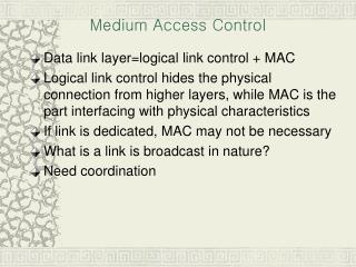
The MAC service • The MAC transmits two types of ‘packets’: • MAC Service Data Unit (MSDU): received from the Logical Link Control (LLC) layer • MAC Management Protocol Data Unit (MMPDU): generated by the MAC entity • Data may be unicast (‘directed’), multicast or broadcast • Packets must be transmitted in order, however, the MAC may transmit packets out of order, provided that • all packets to a particular destination are transmitted in order, and • no more than one packet to any particular destination may be eligible at any time 4
MAC Functions • The MAC entity is responsible for the following: • transmitting MSDUs received from the LLC • fragmentation and de-fragmentation • determining the transmission time for each frame • filtering received frames based on MAC address • performing duplication detection • delivering received MSDUs to the LLC • generating and acting upon management frames as appropriate for the channel access rules in use • specifying various PHY layer parameters (e.g. data rate for transmissions) 5
MAC Addressing • Addresses are 48-bit IEEE 802 addresses • ‘Flat’ address space – no hierarchy • MAC frames carry source and destination addresses • Each BSS also has a BSS ID: • if an AP is present, this is the MAC address of the AP • else randomly generated 8
Frame Format • Address fields vary depending on type of packet: • Address 1 = Intended Receiver • Address 2 = Transmitter • Address 3 = BSS ID, or used to identify Source/Destination in frames crossing DS • Address 4 = Only used in special case (see example 2) 9
Address Fields • The use of the address fields is shown in the table below and varies according to whether the to DS/from DS bits are set: 10
Frame Control Field • Type/Subtype identify the function of the frame: • Types are Control, Data, Management • Control frames include ACK, RTS, CTS • More Fragments bit is set for all fragments of a fragmented MSDU except the last fragment • More Data is used to indicate to a STA (in power save mode or in CFP) that more MSDUs/MMPDUs are buffered for that STA at the AP • Retry bit is set if this frame has previously been (unsuccessfully) transmitted 11
Addressing Example 2 • From A – AP1: • From AP2 – B: • AP1 – AP2 (If DS is 802.11 LAN) : 13
Fragmentation • In order to increase the efficiency of transmissions over a poor channel, MAC may fragment the MSDU • If a fragment of the MSDU is corrupted, previous fragments need not be re-transmitted MPDU MPDU 15
Frame Identification • Each frame is identified by a sequence number and fragment number • All fragments belonging to the same MSDU have the same sequence number • Fragments from the same MSDU have increasing fragment numbers – the first fragment has a fragment number of 0 • The More Fragments bit is set in the header to indicate if this fragment is to be followed by further fragments • The tuple <sending address, sequence #, fragment #> uniquely identifies a frame within a BSS and is used for duplicate frame detection 16
Sequence Control Field • The sequence control field is present in all Data and Management frames 17
Fragmentation Rules • All fragments of an MSDU except the last shall be of the same size • Once an MSDU has been fragmented, the contents of each fragment cannot be changed • When transmitting the first fragment of an MSDU, the transmitting MAC starts a transmit MSDU timer • If the timer expires before the last fragment has been transmitted, then the remaining (unsent) fragments are discarded • aMaxMSDUtransmitLifetime 18
Defragmentation • When the first fragment of an MSDU arrives, the receiver starts a receive timer • If the timer expires, or no timer exists (first fragment was never received), fragments are discarded • Duplicate fragments are acknowledged before being discarded • STA’s must be able to concurrently defragment at least three MSDUs (i.e. they must be able to maintain at least three receive timers) 19
Carrier Sense Overview • The MAC channel access rules are based on Carrier Sense Multiple Access (CSMA) • A mechanism is therefore required to let the MAC know the state of the channel • 802.11 uses two mechanisms: • Physical Carrier Sense: PHY layer provides Clear Channel Assessment service to MAC • Network Allocation Vector (NAV): A virtual carrier sense mechanism using the Duration field in received frames 21
Physical Carrier Sense • When not transmitting or receiving, the Physical layer continuously monitors the state of the channel • The PHY-CCA.indicate primitive indicates to the MAC whether the channel is BUSY or IDLE • This primitive is generated whenever the state of the channel changes 22
Network Allocation Vector (NAV) • The Network Allocation Vector (NAV) is a virtual method for determining the status of the channel (I.e., whether the channel has been acquired by another station) • It consists of a timer which continuously counts down • The value of the NAV is the length of time that is to elapse before the channel becomes IDLE (available) • If the value of the NAV is zero, then according to the NAV the channel is IDLE 23
Updating the NAV • The Duration field in frame contains the length of time for which the transmitting station expects the channel to be busy • The way this is calculated depends on the frame type (Data, ACK, RTS, CTS etc.) • A station shall update its NAV to the value of the Duration field in a received frame if: • the frame is not addressed to that station, and • the value of the Duration field is greater than the current NAV value 24
Principles of the Channel AccessProtocols • The channel access protocols are based on Prioritized Carrier Sense Multiple Access with Collision Avoidance (CSMA/CA) • This involves the following principles: • Carrier Sense Multiple Access: Stations must first listen to the channel to determine that it is clear before transmitting • Random Backoff: a random backoffalgorithm is used to determine the transmission time • Prioritized CSMA/CA: different priorities are accommodated by varying the time for which the channel must be idle before transmitting (higher priority frames wait a shorter idle time) 26
Inter-Frame Spaces (IFS) • 802.11 achieves prioritization of transmissions by varying the length of time that a station must sense the medium idle before (transmitting) considering it to be idle. • This length of time is the Inter-Frame Space (IFS) • High priority frames are transmitted using a shorter IFS than low priority frames 27
802.11 Inter-frame Spaces • 802.11 defines four IFSs (in increasing length/decreasing priority): • Short IFS (SIFS): Used for ACKs and between consecutive fragments of the same MSDU/MMPDU • PCF IFS (PIFS): Used by the PCF procedure • DCF IFS (DIFS): Used by the DCF procedure • Extended IFS (EIFS): Used by the DCF procedure after a frame is received with errors 28
802.11 Channel Access Protocols • Two channel access protocols are defined by 802.11: • Distributed Coordination Function (DCF): fully distributed protocol with no central coordination • Point Coordination Function (PCF): an enhancement to DCF to allow more efficient use of the channel. This uses a centralized control function in the Access Point • The draft supplement 802.11 (e) defines a further enhanced protocol to enable Quality of Service (QoS) requirements to be accommodated 29
Features of DCF • Distributed protocol, requires no centralized coordination • Frames may be transmitted directly, or may be preceded by a RTS/CTS (Ready-to-Send/Clear-to-Send) handshake • All unicast data fragments are positively acknowledged 31
DCF Procedure • A station may transmit if it senses the medium idle for DIFS (DCF Interframe Space) • If medium is busy, station sets random backoff timer • Backoff timer starts running when medium has been idle for DIFS, and runs until either: • medium becomes busy; station pauses timer • timer expires; station can transmit 32
Basic DCF Example • at A, the station senses the medium busy, and calculates a backoff time of 12 slots • the station’s timer runs from B until the medium is sensed busy, and re-starts at C • at D, the timer expires and the station transmits 33
Random Backoff Calculation • The backoff time is a random number of slot times • The number of slot times is a random number drawn from the Contention Window • The contention window is the range of values 0 to CW • After a successful transmission, CW is set to CWmin • After an unsuccessful transmission, the CW is increased (up to a maximum value CWmax) • When a frame has not been transmitted successfully after a given number of attempts the frame is dropped 34
Contention Window - example • The values of CWmin, CWmax vary depending on the PHY used. • e.g. for DSSS PHY: Slot Time = 20s; CWmin= 31; CWmax= 1023 35
Acknowledgements • If a station receives a unicast frame for which it is the destination, it shall immediately send an Acknowledgement (ACK) • ACKs are sent after only a SIFS (Short IFS), and therefore have priority over normal data frames • The original sender of the data frame considers a transmission to have been successful ifand only if an ACK is received • If, after a certain time, an ACK has not been received, the transmission is considered unsuccessful 36
Transmitting Multiple Fragments • A station may maintain control of the medium to transmit multiple fragments of the same MSDU • The station waits only for SIFS before transmitting subsequent fragments 37
RTS/CTS Handshake • For unicast frames, a station may initiate a Request to Send/Clear to Send (RTS/CTS) handshake before transmitting a data frame • The process is as follows: • The transmitting station (source) sends an RTS frame using the normal DCF rules. • The receiving station (destination) responds with a CTS after SIFS • The source station then transmits the data frame after SIFS • On receipt of the data, the Destination station responds with an ACK 38
RTS/CTS and the NAV • In the RTS, the value of the Duration field is set to the total time required for the transmission of the RTS, CTS, data and ACK, including interframe spaces • The Duration field in subsequent frames in the sequence is set to the time until the completion of the sequence (i.e. the end of the ACK) • All stations that receive the RTS and/or CTS will update their NAV and will therefore not transmit until the end of the transmission 39
Multiple Fragments with RTS/CTS • Multiple fragments can be transmitted using RTS/CTS • After the first RTS/CTS exchange, the Data/ACK frames act as ‘virtual RTS/CTS’ • The Duration fields contain the time to the end of the following ACK 41
Benefits of RTS/CTS • RTS/CTS acts as a ‘channel’ check to ensure that Destination can receive the frame • Less overhead is incurred if an RTS/CTS is lost than if the original frame is lost • Overcomes ‘Hidden Node’ problem • RTS/CTS is more useful for longer data frames, since a fixed ‘overhead’ is added to each transmission • Stations have a RTSThreshold length: frames shorter than this length shall not be transmitted using RTS/CTS 42
The ‘Hidden Node’ Problem • A transmits to B • C is out of range of A • When C senses the medium, it finds it idle, and begins to transmit • Collision at B! • With RTS/CTS, C would have updated its NAV on hearing a CTS from B 43
Multicast/Broadcast Data • Multicast or Broadcast data is subject to the following rules: • no ACK is sent in response (i.e. there is no MAC-level recovery/retransmission mechanism) • the RTS/CTS handshake cannot be used • if an AP is present, multicast/broadcast data may be sent via the AP (the transmission to the AP is treated as a unicast transmission) 44
Overview • The Point Coordination Function (PCF) is a contention-free medium access protocol • The PCF is coordinated by a Point Coordinator(PC), which is part of an Access Point (AP) • PCF is ‘backwards-compatible’ with DCF, and can be operated in the presence of stations that use only DCF 46
PCF – Overview (2) • Time is divided into a Contention-Free Period (CFP) and a Contention Period (CP) which alternate • PCF operates only during the CFP • During the Contention Period, DCF is used • The CFP starts at regular intervals (CFP repetition interval), and is separated by a CP 47
PCF Operation • All transmissions in the PCF are controlled by the PC • The PC transmits using the PCF Interframe Space (PIFS), giving them higher priority than DCF transmissions • Data is transmitted as follows: • by the PC to other stations, directly; • from stations to the PC or to other stations, in response to a poll from the PC 48
PCF Transmissions • Frames sent during the PCF can be of the following sub-types: • Data • CF-Poll: Sent by the PC to allow stations to transmit data • CF-Ack: Sent to acknowledge a data frame • Null: sent by a station in response to a CF-Poll, to indicate that it has no data to send • CF-End: sent by the PC to indicate the end of the CFP • A frame can contain more than one of the above functions, as shown in the following table: 49
Frame Functions • The allowable frame combinations are as follows: 50