Download
1 / 31
310 likes | 520 Views
STATUS OF FCI MODELING AND REACTOR APPLICATIONS: ACHIEVEMENTS DURING THE SARNET PROJECT . M. Buck 1 , M. Bürger 1 , M. Leskovar 2 , D. Magallon 3 , R. Meignen 4. 1 IKE, Stuttgart, Germany 2 JSI, Ljubljana, Slovenia 3 CEA Cadarache, France 4 IRSN, Fontenay aux Roses, France.

E N D
STATUS OF FCI MODELING AND REACTOR APPLICATIONS: ACHIEVEMENTS DURING THE SARNET PROJECT M. Buck1, M. Bürger1, M. Leskovar2, D. Magallon3, R. Meignen4 1 IKE, Stuttgart, Germany 2 JSI, Ljubljana, Slovenia3 CEA Cadarache, France 4 IRSN, Fontenay aux Roses, France
Introduction Two distinct phases are essential for large scale steam explosions, characterized by different time scales for the dominant processes • premixing phase • melt flows into water in the form of jets and is progressively transformed into droplets (in a range from a few millimetres to centimetres) which are dispersed into the two-phase coolant • The melt evaporates part of the coolant during this contact and stable vapour film boiling develops around the droplets • Due to relatively slow heat transfer between melt drops and water, such a mixture can be considered as temporarily stable against interactions (no liquid-liquid contact) • Premixing processes take place in a time scale from a few tenths of a second to several seconds.
Introduction (2) • Explosion phase • Action of a trigger can generate a shock wave (local vapor film collapse,rapid heat transfer, fine fragmentation, local pressure buildup) • Explosion waves propagate at supersonic speed through the multiphase mixture, producing further fine fragmentation(to sizes in order of some ten microns) • Large increase of surface and fast heat transfer due to fine fragmentation sustainsthe explosion process • Characteristic time scale of the order of magnitude of a few to tens of milliseconds • Loads on walls determined by duration and magnitude of pressure exerted by the explosion wave • Very high pressures, lasting only for some microseconds, may not endanger the structural integrity • Elevated pressures within the static design limits can be tolerated for almost infinite time
Steam explosion computer codes • Multi-dimensional computer codes required to predict the loads resulting from steam explosions • Within the EU, mainly two lines of codes are applied • MC3D (developed by IRSN):Three-dimensional multi-phase/multi-field code incorporating modelling of premixing and explosion phases • Eulerian 4-field description for premixing (continous melt, drops, water, steam) • Eulerian 4-field description for explosion (melt drops, fragments, water, steam) • IKEMIX for modelling of premixing and IDEMO for explosion (developed by IKE):Two-dimensional multi-phase/multi-field codes • IKEMIX: Eulerian description of water and steam fields, Lagrangean description for melt droplets, representative model for jet • IDEMO: Eulerian 5-field description for heated and unheated coolant, steam, melt droplets and fragments • Three-dimensional extension of IKEMIX and IDEMO presently under way
OECD SERENA Project SERENA - Steam Explosion REsolution for Nuclear Applications Phase 1 (2002-2005, 3.5 years, completed) • Objectives:Reach consensus on major FCI phenomena whose uncertainties impact the predictability of dynamic loading of reactor structures • Main conclusions:FCI code applications to reactor situations showed that: • In the absence of pre-existing loads, in-vessel steam explosion would not challenge the integrity of the vessel • Damage to the cavity is to be expected for ex-vessel explosion • May challenge the integrity of the containment • But, the level of the loads cannot be reliably predicted due to the large scatter of results • Action is required to bring the scatter of the predictions to acceptable levels Phase 2 (started October 2007, 4 years) • Carry out confirmatory research required to reduce uncertainties on these phenomena to acceptable level for risk assessment
Implications for modelling • Conclusions for in-vessel case stands on • Strong void buildup during premixing • Strength of the RPV which allows enveloping of spread in model predictions • Smaller margins for the ex-vessel case imply stronger requirements on the methods and computer tools to be applied in safety studies • Too strong conservatism is impractical • General principles for modelling • Identification of areas and processes of key importance • Modeling of these processes in a best-estimate sense • Strong connection to stepwise validation • Conservatism when necessary • Key role attributed to inherent physical effects that prevent steam explosions from becoming “arbitrarily” strong
Processes determining and limiting the explosion strength • Melt release rate (outflow from RPV) determines amount of fuel which can react with the water • Essentially dependent on the accident scenario, i.e. the mode of melt outflow from the reactor pressure vessel • Failure locations to be expected in the top region of melt pools (heat flux distribution) • Hole formation partly self-limited by outflow and corresponding level decrease • Simultaneous opening of azimuthally distributed breaches rather unlikely, due to the level decrease after a first outflow • Coarse breakup determines the melt content in the mixture, i.e. limits the amount of melt available for rapid heat transfer in an explosion • A large melt pour (large diameter, high velocity) delivers a large amount of melt to the coolant, but breakup of the melt pour will occur only partially • High release velocity will limit the mass involved in the break-up process by more rapid penetration to the bottom • Simultaneous release through multiple melt jets is seen as unlikely under ex-vessel conditions • Importance of water pool height
Processes determining and limiting the explosion strength (2) • Strong tendency towards void buildup in premixing at least for saturated or slightly sub-cooled conditions:large void fractions in the mixture reduce the potential for escalation and propagation of explosion waves • high heat transfer from the hot melt (already from radiation heat transfer) • limited steam removal from the mixture and water (due to interfacial friction) • limited triggering potential by preventing direct melt/water contact • Partial solidification of melt drops prevents fine fragmentation during the explosion and is expected to result in a strong reduction of the explosion strength • Early crust formation at the surface of the falling drops expected for ceramic corium melts, due to the low thermal conductivity of the material and large heat losses already from radiation “material effect” can to a large extent be attributed to solidifcation (together with differences in coarse breakup) • Large uncertainties with respect to the magnitude of this effect presently exist, both concerning experimental data and modeling
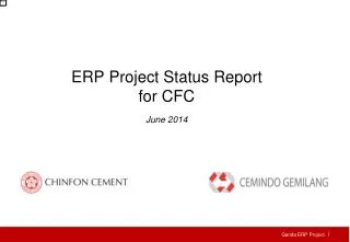
Effect of void on explosion propagation • Series of explosion calculations carried out using the explosion code IDEMO to illustrate the effect of an increasing void content on the potential of a given pre-mixture to support the escalation and propagation of a steam explosion • Calculations performed in simple 2D cylindrical geometry for a water pool of 2 m height and a mixture zone, that would establish around a fragmenting melt jet, with a radial extension of 60 cm • Different conditions in the pre-mixture assumed • melt volume fraction varied between 0.3% and 3% • void fraction varied between 30% and 70% • The explosions were triggered by imposing an initial overpressure in a few cells at the bottom centre. Mixture configuration used for parametric study with IDEMO on void influence on explosion propagation.
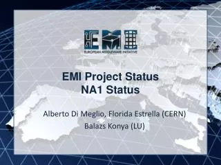
Effect of void on explosion propagation (2) • Clear dependency of explosion strength on void: Maximum pressures decrease practically linearly with increasing void • No escalation for void fractions of 60% and above • Ability to escalate depends also to some extent on the trigger strength: • with weaker trigger (5 MPa no escalation with void > 50%) • With stronger trigger (20MPa) still no escalation for void fractions > 60% trigger pressure: 10 MPa Maximum pressures Maximum wall pressures
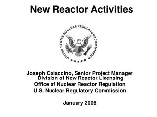
Ex-Vessel reactor case calculations • Steam explosion in typical pressurized water reactor cavity studied by JSI using the MC3D computer code • Reactor cavity modeled in a simplified 2D geometry • axial symmetric model appropriate for a central melt pour • 2D slice model for sideways pour • 2D representation of the cavity implies a considerable conservatism concerning the explosion loads radius of cylindrical part r ≈ 2.5 m, height z ≈ 13 m, length x ≈ 10.5 m,
Initial conditions and calculated cases • Wide spectrum of different relevant scenarios analyzed varying melt pour location, primary system overpressure and cavity water sub-cooling • The premixing phase was simulated for 10 seconds after the start of the melt release • For each premixing simulation, a number of explosion simulations were performed, triggering the pre-mixture at different times.
Results of ex-vessel reactor calculations • Stronger steam explosions at higher water sub-cooling (condensation hinders the void build-up) • Stronger steam explosions in the initial stage of the melt release (void build-up after some time due to reduction of subcooling) • For side melt pour cases stronger explosions with a depressurized primary system (with pressurized primary system melt is ejected sideward on the cavity wall, hindering the formation of a pre-mixture, also gas flow through the vessel opening into the cavity forms a highly voided region below the reactor vessel) Maximum pressures and pressure impulses calculated for the cntral pour case for different trigger times
Results of ex-vessel reactor calculations (2) Maximum pressures and pressure impulses calculated for different melt pour locations • Effect of partial solidification of melt droplets studied in addition for the strongest case C2-60, considering different corium droplet bulk temperatures, below which the fine fragmentation process is suppressed Solidification has significant impact with strong reduction of explosion strength • Maximum calculated pressures and pressure impulses for some scenarios significantly higher than loads calculated in SERENA Phase 1 • For sideways pour slice geometry underpredicts venting and pressure relief • In central pour case, a more detailed analysis showed that e.g. in the strongest case C2-60 an off-centre trigger yielded symmetric convergence and very high peak pressures at centreline Further analysis required Solidification influence on maximum pressures and impulses (case C2-60)
Current challenges for modelling • Buildup of a high void in the mixture identified in experiments and reactor case studies as most important mechanism to reduce the strength of explosions under saturated or weakly subcooled conditions • In ex-vessel scenarios, stronger water subcooling to be expected for some scenarios other points become equally important • Low void fractions at least during the initial phase of the melt-water interaction ? • Effect of partial solidification of melt drops ? • Influence of subcooling on solidification ? • Current status can be best illustrated by means of recent pre-test calculations for the planned new experiments in KROTOS and TROI
Preliminary analysis • Effect of subcooling in past KROTOS testsMaximum pressure Energy conversion ratio • Effect of subcooling not obvious • Most energetic Alumina test at nearly saturation; lack of data for moderate subcooling • No data for moderate and low subcooling for Corium Fig. IRSN
Preliminary analysis • Correlation between fuel debris fraction and energeticsMaximum pressure Energy conversion ratio • Lower fuel debris fraction (d<100 μm) for corium (~20%) Fig. IRSN
Drop Fragmentation in KROTOS • Evolution of melt droplet and fragment cloud calculated with MC3D • 3 mm corium drop fragmenting under the effect of a 15 MPa shock wave: initial state (left) and result at 1.5 ms (right). • Visualization shows extent of the fragment cloud (volume surface, corresponding to 1% melt fraction) and melt fraction (pseudo-color, coherent droplet corresponds to dark red) Fig. IRSN/MC3D
Comparison of fuel drop fine fragmentation between corium and alumina Evolution of the masses of a typical Corium (3 mm) and Alumina drop (1 cm) in KROTOS under action of a 150 bar shock wave • Corium fragments faster than alumina! fragmentation almost complete after 1 ms, sufficient to obtain full fragmentation even for mild explosions Low debris fraction in corium tests rather indication for important solidification Fig. IRSN/MC3D
5 kg of melt 1-D geometry New release device X-ray radioscopy External trigger UO2-ZrO2-Steel-Zr-FP 20 kg of melt 2-D geometry Intermediate catcher Tomography External trigger TROI test assembly KROTOS test section KROTOS and TROI test facilities
KROTOS Fig. JSI Pre-test calculations • Simulations performed for different water subcoolings • ambient T=20°C to saturation T=144°C at 4 bar • KROTOS: 5 kg of corium melt (70% UO2, 30% ZrO2), orifice diameter 3 cm, TROI: 20 kg (same melt composition) orifice diameter 5 cm. • Different approach in melt release modeling • CEA, IRSN • Rough modelingof injectiondevice • IKE, JSI • Prescribedcalculatedinjectionvelocity • Different melt-waterimpact velocities
Jet breakup and melt penetration • Complete jet breakup obtained in all calculations for KROTOS and TROI) • Influence of subcooling on jet breakup and melt penetration small (only once jet totally fragmented) • Exception in MC3D calculation of IRSN for saturated water: completely different behavior; in KROTOS melt stays in suspension for long time • Terminal droplets velocity higher with higher subcooling Melt penetrationKROTOS Fig. CEA/MC3D
Solidification modeling • Modeling of solidification effects: • IKEMIX • Lagrangean description of melt droplet phase, semi-analytical approach to calculate temperature profile and crust thickness in individual drops • drop not considered in explosion calculation if crust thickness above given threshold (about 10% of drop radius) • MC3D • Fine fragmentation inhibited once drop average temperature below given threshold • Default: Threshold = T_solidus (applied by CEA, and IRSN) • JSI: Threshold = T_liquidus (approximately accounts for solidification) • Crust model development underway (Ph.D. Thesis)
Effect of solidification • Liquid melt mass in mixtureKROTOS TROI • At time of melt-bottom contact (MBC) most of melt is premixed • KROTOS: All melt in mixture at MBC (up to 5 kg), TROI: All melt in mixture soon after MBC (up to 11 kg) • In IKEMIX calculations: Whatever the subcooling, an important fraction of melt is solidified • Solidification ratio ranging from 60 to 80% • Subcooling reduces amount of liquid melt by factor of ~2 • JSI calculation with MC3D: Up to 40% solidified for max. subcooling DTsub DTsub Fig. IKE/IKEMIX
Void in Premixture • Void in mixtureKROTOS TROI • At moderate to large subcoolings amount of void predicted in all calculations is quite limited and does not inhibit an explosion Fig. IKE/IKEMIX DTsub = 40 K DTsub = 120 K DTsub = 120 K DTsub = 40 K
Explosionresults • Pressure and Pressure impulseKROTOS TROI • Calculations where solidification is not considered reveal a weaker effect on energetic regarding subcooling • Different effects of subcooling on maximum pressures in different calculations • Partly compensating effects of void and solidification in JSI calculations with MC3D • IDEMO results clearly reflect solidification effect: Decreasing explosion strength with increasing subcooling due to less liquid mass in mixture Fig. IRSN/MC3D Fig. IRSN/MC3D
Conclusions from pre-test calculations • The first (preliminary) calculations revealed uncertainties and differences concerning major relevant effects, e.g.: • Different jet release velocities assumed in the calculations and their influence on the droplet sizes, melt distribution and finally optimum timing for triggering • Amount of solidification and its influence on the explosion strength • Void formation and its influence on the explosion strength, especially at moderate subcooling • This defines the need for the further clarification process • The Analytical Working Group (AWG) established in the actual OECD SERENA Project shall give an improved basis for this
SERENA Phase 2 SERENA Phase 2 (started October 2007, 4 years) • Objectives:To reduce the scatter of the predictions in order to be able to put safety margins to containment failure by: • Providing the missing data on the key phenomena for code validation • Spatial distribution of fuel and void during premixing and at the time of explosion in various conditions • Explosion behaviour of a large spectrum of corium melts representative of accident scenarios • Improving modelling on the basis of the new data so that consistent predictions of cavity loading by ex-vessel steam explosion are obtained • Experimental program • Complementary KROTOS (CEA) and TROI (KAERI) test facilities • 12 tests will be performed, six in each facility • Analytical program • Increasing the capabilities of FCI models/codes for use in reactor analyses by complementing the work in Phase-1 through integrating the results of the Phase-2 Experimental program
Partners in SERENA Phase2 • Partners from 11 countries are participating: • Belgium (Tractebel-Engineering SUEZ) • Canada (AECL) • Finland (VTT) • France (CEA, IRSN) • Germany (GRS, IKE) • Japan (JNES) • Korea (KAERI, KINS) • Slovenia (JSI) • Sweden (SSM, KTH) • Switzerland (PSI) • USA (US NRC, UWM)
Experimental program • The complementary and innovative features of KROTOS (CEA) and TROI (KAERI) facilities will be used • KROTOS for investigating the FCI characteristics of prototypical corium melts in one-dimensional geometry • Suitable for computer code model improvement • TROI for investigating the FCI behaviour in reactor-like conditions by having more mass and multi-dimensional melt water interaction geometry • Suitable for validating the capability of the computer codes in reactor-like situations • Improved features in KROTOS and TROI • Improved release conditions in both KROTOS and TROI (FARO-type release device) • Advanced measurement techniques for determining component distribution in pre-mixing • High energy X-rays in KROTOS • Electrical tomography in TROI • Improved physical and chemical analysis of debris to identify “material effects” • Investigation of physico-chemical behaviour of the materials
Analytical program • Increasing the capabilities of FCI models/codes for use in reactor analyses by complementing the work performed in Phase-1 through integrating the results of the Phase-2 Experimental program • Work oriented at fitting for purpose for safety analysis and elaboration of the major effects which reduce the explosion strength • Analytical working group (AWG) established • Participating organizations: • CEA, IKE, IRSN, JSI, KAERI, KINS, KTH, Tractebel, UWM, VTT • Main tasks of the AWG are: • Performing pre- and post-test calculations in support of test specification and analysis • Improving the common understanding of those key phenomena that are believed to have a major influence on the FCI process • Addressing the scaling effect and application to the reactor case • Demonstrating the progress made in SERENA Phase-2 as compared with Phase-1 (in particular on reducing the scatter of the predictions) by repeating the “ex-vessel reactor exercise”