Download
1 / 15
150 likes | 307 Views
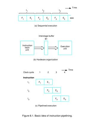
T. ime. I. I. I. 1. 2. 3. F. E. F. E. F. E. 1. 1. 2. 2. 3. 3. (a) Sequential execution. Interstage buffer. B1. Instruction. Ex. ecution. fetch. unit. unit. (b) Hardware organization. T. ime. Clock cycle. 1. 2. 3. 4. Instruction. I. F. E. 1. 1. 1. I. F.

E N D
T ime I I I 1 2 3 F E F E F E 1 1 2 2 3 3 (a) Sequential execution Interstage buffer B1 Instruction Ex ecution fetch unit unit (b) Hardware organization T ime Clock cycle 1 2 3 4 Instruction I F E 1 1 1 I F E 2 2 2 I F E 3 3 3 (c) Pipelined execution Figure 8.1. Basic idea of instruction pipelining.
E:Execute (ALU) (b) Position of the source and result registers in the processor pipeline
T ime Clock c ycle 1 2 3 4 5 6 7 8 F D E W I 1 1 1 1 1 F I (Branch) D E 2 2 2 2 F D X I 3 3 3 F X I 4 4 F D E W I k k k k k F D E I k+ 1 k+ 1 k+ 1 k+ 1 (a) Branch address computed in Execute stage T ime Clock c ycle 1 2 3 4 5 6 7 F D E W I 1 1 1 1 1 F D I (Branch) 2 2 2 F X I 3 3 F D E W I k k k k k F D E I k+ 1 k+ 1 k+ 1 k+ 1 (b) Branch address computed in Decode stage Figure 8.9. Branch timing.
T ime Clock c ycle 1 2 3 4 5 6 7 8 Instruction Decrement F E Branch F E Shift (delay slot) F E Decrement (Branch tak en) F E Branch F E Shift (delay slot) F E Add (Branch not tak en) F E Figure 8.13. Execution timing showing the delay slot being filled during the last two passes through the loop in Figure 8.12.
T ime 1 2 3 4 5 6 Clock cycle Instruction I (Compare) F D E W 1 1 1 1 1 I (Branch>0) F D /P E 2 2 2 2 2 I F D X 3 3 3 I F X 4 4 I F D k k k Figure 8.14. Timing when a branch decision has been incorrectly predicted as not taken.
LT ST Branch taken (BT) BNT LNT BT LT Branch not taken (BNT) (a) A 2-state algorithm BT LNT SNT BNT BNT BNT BT BT BT BNT (b) A 4-state algorithm Figure 8.15. State-machine representation of branch prediction algorithms.
T ime Clock c ycle 1 2 3 4 5 6 7 Load F D X + [R1] [X + [R1]] [[X + [R1]]] W F orw ard Ne xt instruction F D E W (a) Complex addressing mode Add F D X + [R1] W Load F D [X + [R1]] W Load F D [[X + [R1]]] W Ne xt instruction F D E W (b) Simple addressing mode Figure 8.16. Equivalent operations using complex and simple addressing modes.
Figure 8.18. Datapath modified for pipelined execution, with Interstage buffers at the input and output of the ALU.
T ime Clock c ycle 1 2 3 4 5 6 7 I (F add) F D E E E W 1 1 1 1A 1B 1C 1 I (Add) F D E W 2 2 2 2 2 I (Fsub) F D E E E W 3 3 3 3A 3B 3C 3 I (Sub) F D E W 4 4 4 4 4 (a) Delayed write T ime Clock c ycle 1 2 3 4 5 6 7 I (F add) F D E E E W 1 1 1 1A 1B 1C 1 I (Add) F D E TW W 2 2 2 2 2 2 I (Fsub) F D E E E W 3 3 3 3A 3B 3C 3 I (Sub) F D E TW W 4 4 4 4 4 4 (b) Using temporary registers Figure 8.21. Instruction completion in program order.
Figure 8.23. Main building blocks of the UltraSPARC II processor.
ADDcc R3, R4, R7 R7 [R3] + [R4], Set condition co des BRZ,a Lab el Branch if zero, set Ann ul bit to 1 F CMP F1, F5 FP: Compare [F2] and [F5] F ADD F2, F3, F6 FP: F6 [F2] + [F3] FMO Vs F3, F4 Mo v e single precision op erand from F3 to F4 . . . Lab el FSUB F2, F3, F6 FP: F6 [F2] [F3] LDSW R3, R4, R7 Load single w ord at lo cation [R3] + [R4] in to R7 . . . (a) Program fragment ADDcc R3, R4, R7 BRZ,a Lab el F CMP F1, F5 FSUB F2, F3, F6 (b) Instruction grouping, branch taken ADDcc R3, R4, R7 BRZ,a Lab el F CMP F1, F5 F ADD F2, F3, F6 (c) Instruction grouping, branch not taken Figure 8.25. Example of instruction grouping.
Main External cache memory Instructions Data Instruction cache Load/store queue Instruction b uf fer Elastic interf ace Internal Data re gisters and cache e x ecution units Figure 8.30. Execution flow.
Table 8.1 Examples of SPARC instructions. Instruction Description ADD R5, R6, R7 In teger add: R7 [R5] + [R6] ADDcc R2, R3, R5 R5 [R2] + [R3], set condition co de flags SUB R5, Imm, R7 In teger subtract: R7 [R5] Imm (sign-extended) AND R3, Imm, R5 Bit wise AND: R5 [R3] AND Imm (sign-extended) X OR R3, R4, R5 Bit wise Exclusiv e OR: R5 [R3] X OR [R4] F ADDq F4, F12, F16 Floating-p oin t add, quad precision: F12 [F4] + [F12] FSUBs F2, F5, F7 Floating-p oin t subtract, single precision: F7 [F2] [F5] FDIVs F5, F10, F18 Floating-p oin t divide, single precision, F18 [F5]/[F10] LDSW R3, R5, R7 R7 32-bit w ord at [R3] + [R5] sign extended to a 64-bit v alue LD X R3, R5, R7 R7 64-bit extended w ord at [R3] + [R5] LDUB R4, Imm, R5 Load unsigned b yte from memory lo cation [R4] + Imm, the b yte is loaded in to the least significan t 8 bits of register R5, and all higher-order bits are filled with 0s STW R3, R6, R12 Store w ord from register R3 in to memory lo cation [R6] + [R12] LDF R5, R6, F3 Load a 32-bit w ord at address [R5] + [R6] in to floating p oin t register F3 LDDF R5, R6, F8 Load doublew ord (t w o 32-bit w ords) at address [R5] + [R6] in to floating p oin t registers F8 and F9 STF F14, R6, Imm Store w ord from floating-register F14 in to memory lo cation [R6] + Imm BLE icc, Lab el T est the icc flags and branc h to Lab el if less than or equal to zero BZ,pn xcc, Lab el T est the xcc flags and branc h to Lab el if equal to zero, branc h is predicted not tak en BGT,a,pt icc, Lab el T est the 32-bit in teger condition co des and branc h to Lab el if greater than zero, set ann ul bit, branc h is predicted tak en FBNE,pn Lab el T est floating-p oin t status flags and branc h if not equal, The ann ul bit is set to zero and the branc h is predicted not tak en