Download
1 / 32
330 likes | 439 Views
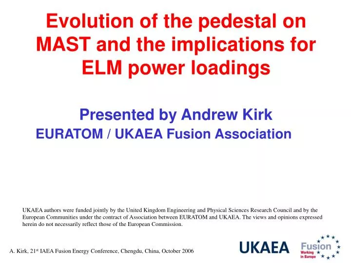
Evolution of the pedestal on MAST and the implications for ELM power loadings Presented by Andrew Kirk EURATOM / UKAEA Fusion Association.

E N D
Evolution of the pedestal on MAST and the implications for ELM power loadings Presented by Andrew Kirk EURATOM / UKAEA Fusion Association UKAEA authors were funded jointly by the United Kingdom Engineering and Physical Sciences Research Council and by the European Communities under the contract of Association between EURATOM and UKAEA. The views and opinions expressed herein do not necessarily reflect those of the European Commission.
ITER Size of type I ELM Energy Loss Understanding the size of ELM energy loss on future devices such as ITER is essential Most predictions are based on scaling data from present devices There is a large uncertainty due to our lack of understanding of the processes involved.
Outline • Extension of MAST operational space to lower pedestal collisionality • The filament structures observed during type I ELMs and their relevance to the ELM energy loss process • Working towards a model for ELM energy losses
Contribution from MAST Most MAST discharges have a high pedestal collisionality due to a low temperature pedestal and the energy losses due to ELMs are up to 5 % of the pedestal energy MAST data
Contribution from MAST A dedicated campaign using optimised fuelling and vessel conditioning has been used to increase the temperature pedestal and extend the MAST data set to lower collisionalities New data Agrees well with the scaling observed on other devices
Pedestal profiles The lowest pedestal collisionality shot (*ped ~ 0.08) produced to date has:
Stability analysis Edge stability calculations, using the 2D ELITE code, have been performed on these profiles, which were obtained just before an ELM A parameter scan shows that the point lies close to the ballooning boundary - Characteristics associated with type I ELMs
Comparison of the pedestal at high and low * Low * High * (kPa/N) 29.0 30.3 (N) 0.035 0.017 Similar pressure gradient but low * case is > 2xbroader
Comparison of ELM losses at high and low * Low * High * Large Te No Te But why are ELM losses greater at lower collisionality ?
Spatial structure during type I ELMs At the last IAEA it was known that filament structures exist during ELMs MAST NSTX ASDEX Upgrade DIII-D but what role do they play in the ELM loss mechanism ?
Studies of the evolution of the filaments during type I ELMs on MAST MAST has installed new imaging systems and a new edge TS system to study the evolution of the filaments 10 kHz frame rate
Analysis of the images 3-D field lines are mapped onto the 2-D images taking into account the distortion of the system.
Analysis of the images 3-D field lines are mapped onto the 2-D images taking into account the distortion of the system.
Comparison of type I ELMs at different * 5 ms exposure 10 ms exposure Very little difference in the size, number or the behaviour of the filaments
Reduced views allows the evolution of the filaments to be studied 100 kHz frame rate
Evolution of the filaments The toroidal and radial location of the filaments are tracked in consecutive frames The filaments are observed to rotate in the co-current direction, decelerate toroidally and accelerate out radially The width of the filament is ~ constant in time
Evolution of the filaments The filaments exist during the time that particles are lost from the pedestal
Summary of the evolution of ELM filaments • Filaments exist for the entire “ELM loss” time • Individual filaments detach from the LCFS at different times • Follow the local field line, decelerate toroidally and accelerate radially. • The width perpendicular to the field line is ~ constant in time But what is the energy/particle content of the filaments?
The energy/particle content of the filaments 0. Pre-ELM pedestal
The energy/particle content of the filaments 0. Pre-ELM pedestal 1. Formation of tail
The energy/particle content of the filaments 0. Pre-ELM pedestal 1. Formation of tail 2. Radial expansion - no local loss in pedestal density Energy in largest filament < 2.5 % WELM
The energy/particle content of the filaments 0. Pre-ELM pedestal 1. Formation of tail 2. Radial expansion - no local loss in pedestal density 3. Filament appears to detach at mid-plane (leaving a depression) Energy in largest filament < 2.5 % WELM
The energy/particle content of the filaments 0. Pre-ELM pedestal 1. Formation of tail 2. Radial expansion - no local loss in pedestal density 3. Filament appears to detach at mid-plane (leaving a depression) 4. Accelerates radially – particle content decreases exponentially with distance
A possible mechanism for type I ELM energy losses • Filaments remain close to the LCFS for 50 - 200 ms - during this time they enhance transport into the SOL. • Individual filaments detach during this period - slow toroidally and accelerate radially. • At the time of detachment each filament contains up to 2.5 % WELM • As the filaments travel out radially this content is reduced by parallel transport to the targets
Energy lost through the filaments Assume that duringtELMthe filament acts as a conduit for losses from the pedestal region tELM(MHD) ~(tA2tE)1/3 ~100 ms (MAST) Total particles down the filaments Area of filament Number of filaments
Energy lost through the filaments Assume that duringtELMthe filament acts as a conduit for losses from the pedestal region tELM(MHD) ~(tA2tE)1/3 ~100 ms (MAST) Total particles down the filaments ELM energy loss sfilament, #filand pedestal T and n measured
Results from the simple model MAST Given the simplifications and approximations used there is moderate agreement with the data But what about other devices?
Results from the simple model Extrapolation of model to JET Assume #fil=10 and filament a Size ~ 20 cm The next step should be to use our improved knowledge of the ELM loss process to build a “real” model
Summary • High temperature pedestal plasmas have been achieved on MAST with collisionalities one order of magnitude lower than in previous discharges. • The structure and evolution of the filaments observed during type I ELMs is similar at both high and low collisionalities • The evolution of the filaments have been tracked through individual ELMs showing how they remain attached to the LCFS, decelerate toroidally and accelerate radially and at the time of detachment each filament carries up to 2.5 % of WELM • Based on this evolution a mechanism for ELM energy loss has been proposed and a simple ELM energy loss model derived – the next step is to build a “real” predictive model.