Download
1 / 36
540 likes | 1.92k Views
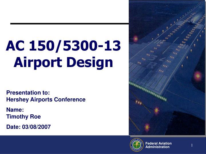
AC 150/5300-13 Airport Design. Presentation to: Hershey Airports Conference Name: Timothy Roe Date: 03/08/2007. Overview. Precision Obstacle Free Zone (POFZ) Implementation TERPS Obstacle Clearance Surface Protection Implementation Departure Surface (40:1) Implementation

E N D
AC 150/5300-13 Airport Design Presentation to:Hershey Airports Conference Name:Timothy Roe Date: 03/08/2007
Overview • Precision Obstacle Free Zone (POFZ) Implementation • TERPS Obstacle Clearance Surface Protection Implementation • Departure Surface (40:1) Implementation • One Engine Inoperative (OEI) • Change 11 • AC 150/5300-13 Rewrite • Airport Survey Requirements
Precision Obstacle Free Zone (POFZ) • The purpose of the POFZ is to protect the area of short final during very low ceilings of less than 300 feet and visibilities of less than ¾ statute mile or less than 4,000 feet Runway Visual Range (FAA Notice JO 7110.460, January 22, 2007)
There are currently a couple of hold lines protecting runways and taxiways and the ILS Critical Area this does not change … • What potentially does change is the location of the ILS critical area hold lines and appropriate signage • The POFZ may require the airport to position these lines so that during low visibility operations vehicles remain outside the POFZ • If an aircraft or vehicle transgresses the POFZ then ATC must advise any aircraft on a vertically guided approach within 2 miles of the threshold
Final Approach “Y” Surface 300’ 300’ Final Approach “Y” Surface • Another set of surfaces is the TERPS Obstacle Clearance Surface (OCS) comprised of “W”, “X”, and “Y” surfaces • These surfaces are designed to protect both sides of the the final approach course when the reported ceiling is 800 feet or less and the visibility is 2 SM or less and the aircraft on final is within 2 NM of the threshold • These protected surfaces are important for an aircraft executing a missed approach when its momentum may carry it below the DA before the pitch, flaps, and engine power can begin a climb. This loss is such that the tail heights of taxiing and those holding for departure could be a factor.
40:1 Departure Surface • Establish a consistent 40:1 Obstacle Clearance Surface (OCS) standard • Provide departure obstacle information to aircraft operators for all 40:1 penetrations • Revise both the internal coordination procedures and the policy criteria governing the circularization process in the OE/AAA program.
40:1 Departure Surface • Consistent with TERPS and 14 CFR guidance • Added to Appendix 2 • Applicable to designated instrument runways with departure procedures (Airports perspective) • “The applicability of the surface table A2-1 is dependant on the designation of primary runway(s) for departure. The Airport Sponsor through the ADO or Regional Airports Division , will identify the runway end(s) intended primarily for instrument departures to the RAPT. • The determination of primary runway(s) for departure does not prohibit or negate the use of other runways . It only identifies the applicability of the A2-1 surface to the runway end(s). “
One Engine Inoperative Departure Surface • One Engine In-Operable (OEI) Survey Surface: • Applicable at all runway ends used for air carrier departures • Surface penetrations will be made available to all air carriers at the airport • Does not take effect until January 1,2008
Runway to Parallel Taxiway Separation • In support of Agency’s commitment to ensure safe precision approach and landing operations, policy clarification is needed, and the Airports Design A/C, TERPS and other guidance must be consistent (i.e., taxiing, parked and holding aircraft are obstacles)
Construction of New Runways/Parallel Taxiways • All CAT I operations • 400 ft separation (500 ft for Group VI) • CAT II/III Operations • Groups I-IV aircraft - 400 ft separation • Group V aircraft - 500 ft separation* • Group VI aircraft - 550 ft separation* *if Airport elects to proceed with construction
End Around Taxiways • In an effort to increase operational capacity, airports have added dual and sometimes triple parallel runways, which can cause delays when outboard runway traffic has to cross active inboard runways to make its way to the terminal. • To improve efficiency and provide a safe means of movement around the departure end of a runway, it might be feasible to construct a taxiway that allows aircraft to transition around the ends of the runway.
End Around Taxiways • End-around taxiways must remain outside of the standard runway safety area (RSA), which extends 1,000 feet along the centerline extended of the departure end of the runway (DER). • EAT must be entirely outside of the ILS critical area.
End Around Taxiways • An airspace study for each site should be performed to verify if the tail height of the critical design group aircraft operating on the EAT does not penetrate any FAA Order 8260.3 TERPS surface and meets the requirements of 14 CFR 121.189 for the net takeoff flight path to clear all obstacles either by a height of at least 35 feet vertically, or by at least 200 feet horizontally within the airport boundaries. • The placement and configuration of EATs must take into account additional restrictions to prevent interfering with navigational aids, approaches and departures from the runway(s) with which they are associated.
End Around Taxiways • In order to avoid potential issues where pilots departing from a runway with an EAT might mistake an aircraft taxiing on the EAT for one actually crossing near the departure end of the runway, a visual screen type device may be required, depending on the elevation changes at a specific location. Through a partial or complete masking effect, the visual screen will enable pilots to better discern when an aircraft is crossing the active runway versus operating on the EAT.
End Around Taxiways • A visual screen is required for any new EAT unless the elevation of the EAT centerline, at a point in line with the extended runway centerline, is at least 29 feet below the elevation at the DER, so the terrain creates a natural masking of the aircraft on the EAT.
Change (Clarification) 11 - RPZ • Actually it is a clarification of current policy, not something new ! • Soon to come …(still in DRAFT) • Central Portion of the RPZ • Consists of a portion of the Runway OFA and OFA extension • Parking areas and associated appurtenances must be located outside the Central portion of the RPZ (previously it said OFA extension) • No changes to the standards regarding congregations of people
Change (Clarification) 11 - RPZ • New subparagraph under Land Use • At some airports, parking areas are already established in the central portion of the RPZ on land controlled by the airport. In such cases, the airport operator should make every effort to remove these parking areas, particularly when parking involves frequent turnover and the regular presence of persons. This should be done when the airport operator next has the ability to change the use of the property, such as when the lease expires. Difficulty finding alternative parking in other than prohibited areas is normally not sufficient justification for an approval of a modification of standards.
Airport Design RewriteScope and Schedule • Complete Re-Write and Reorganization • Last major re-write – 1989 • Define Basic Concepts • Guidelines for re-write and future revisions • Preliminary Comments • Project Notice, October, 2004 • Over 300 comments received • Regional/HQ Team Formed January, 2006 • Informal Industry Coordination • Draft Outline, August, 2006 • First Draft, 2007*
Standard Design Standards • What are the goals and objectives? • Safety is highest priority • Aviation demand • Environmental protection • Economic viability • How are standards used by FAA? • Federal funding • ALP development & grant obligations • CFR Part 139 • Airspace evaluation
Standard Design Standards: What is a Standard? • Must relate to FAA goals • Safety • Utility • Efficiency • Do not regulate aircraft operations • Must have rationale and justification for each • Modification of Standards • Clarify how, why, and when • Must maintain an acceptable level of safety • Not appropriate for occasional use by larger aircraft
Chapters Regulatory Requirements and Definition of Terms Design and Planning Considerations, Airport Geometry Runway Design Taxiway and Taxilane Design Aprons Navigational Aids Appendices Glossary Aircraft characteristics Compass calibration pad Effect of jet blast Wind analysis Acronyms Other Considerations Limit the number of appendices Comprehensive– everything about airport design Use external references whenever possible (provide hyperlink) Limit cross-referencing within the document– everything should be in one place Advisory Circular Organization
Airport Surveying
Vision Enhance airport surveying by establishing a standardized repeatable program to capture data in an appropriate format both accurately and consistently
Purpose • Increase the Number of Surveys Conducted Annually • Provide data for a standard GIS database capable of supporting the needs of the FAA as a whole • Reduce the FAA’s use of NGS for field surveys and transition the requirements for aeronautical and airport surveys to commercial enterprises • Allow surveys conducted by commercial enterprises to use State & Local Aviation Resources as well as Federal Grants. • Standardize the process of airport and aeronautical surveys in a cost-effective and expedited manner • Move toward the implementation of Digital ALPs and OC Drawings.
Surveying Objectives • Create a Standardized Process for conducting airport and aeronautical surveys – Advisory Circulars • AC 150/5300 –16 “General Guidance and Specifications for Aeronautical Surveys: Establishment of Geodetic Control and Submission to the National Geodetic Survey” • AC150/5300 – 17 “General Guidance And Specifications For Aeronautical Survey Airport Imagery Acquisition And Submission To The National Geodetic Survey” • AC 150/5300-18 “General Guidance and Specifications for Submission of Aeronautical Surveys to NGS: Field Data Collection and Geographic Information System (GIS) Standards “
Surveying Objectives • Guidance and specifications allowing airports to produce digital ALP data meeting FAA needs • Develop tools for airports and surveyors to capture and provide survey data in digital form • Provide a means to acquire essential data as it is created in a digital form with associated metadata • Develop technical guidance, instructions and templates on contracting out and/or conducting aeronautical surveys for airport sponsors
Alphabet Soup or Survey Requirements ??? • ANA-LPV • ANAPC • PIR • CGR • BV • AV • C • D “Say What ????
Integrated Survey Surface Objective • Develop a set of integrated surfaces meeting the data collection and maintenance requirements of the FAA and its customers
Draft Draft
What Appendix 16 Criteria Applies to LPV ? • LPV approaches are defined as APV approaches, so typicallyTable A16-1B Airport Infrastructure applies. • Parallel Taxiways are required for an instrument procedure with less than 1 statue mile visibility
What Appendix 16 Criteria Applies to LPV ? • Approach Lights … • Table A16-1B states they are a required element for visibilities less than 1 SM … except for LPV (Note 11)
LPV Approaches to 200 foot DA • LPV approaches to a Decision Altitude of 200 feet are authorized where the appropriate ILS infrastructure is in place. • At locations where the proposed procedure would not be an overlay of an ILS, the requirements of Appendix 16, Table 16-1A must be met • Precision Infrastructure for a 200 foot DA.
Questions Office of Airport Safety and Standards Airport Engineering (AAS-100) 800 Independence Ave. SW Washington, DC. 20591 Telephone: 202.267.7669 or Fax: 202.267.3688 National Resource Expert for Airport and Airspace Issues: Bob Bonanni