Download
1 / 31
310 likes | 441 Views
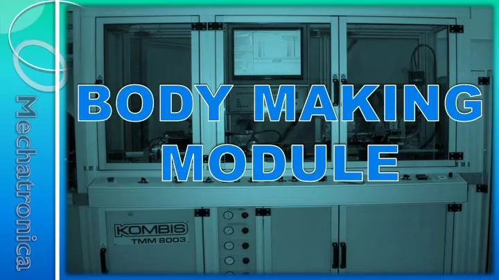
BODY MAKING MODULE. Purpose. Body Making module is designed for bending the laminated foil film in the shape of a tube, for welding the side seam and for cutting bodies with the necessary length. Main components. Body Making module consists of the following parts and mechanisms:

E N D
Purpose Body Making module is designed for bending the laminated foil film in the shape of a tube, for welding the side seam and for cutting bodies with the necessary length.
Main components Body Making module consists of the following parts and mechanisms: 1. control panel 2. mandrel bending mechanism 3. welding mechanism 4. driving mechanism 5. supporting transporter 6. Cooler 7. incremental encoder 8. body reshaping roll 9. mark-sensor 10. reshaping mechanism 11. cutting mechanism
Main components 1. Control panel Onto the control panel are placed the buttons, switches and regulators for control of Body Making mechanism. It is described in details in next picture:
2. Mandrel It is designed to form the foil in shape of tube and to hold the foil during the welding and the cooling of the seam. The mandrel is replaceable for the different diameters of the bodies as well as for the different materials- PBL and ABL foil. The mandrel consists of: body with rolls, extender, carrier with bending sleeve, cooler and guide.
There is a mounted rolls into the body of the mandrel, which purpose is to press the foil during welding . • The purpose of the extender is to support the foil when moving from the driving mechanism. • The purpose of the carrier is to fixture the mandrel onto the machine’s construction and carry the bending sleeve. • The purpose of the cooler is to lead on the cooling water into the mandrel’s body. • The purpose of the guide is to determine the position of the foil according to the mandrel and to regulate the diameter of the body. The regulation is been accomplished through spinning the guide around its axis.
It serves for welding the seam of the body. It consists of 2 positions- one for PBL welding and one for ABL welding. On the first position is performed the flushing ofhot air into the area of welding seam, also pressing and following cooling by cooling roller, that assists to reach the necessary strength of the seam. The air funnel is mounted over screw slide-ways with the help of which could be precisely regulated its position according the mandrel and the pressure on the foil. It is connected by means of a metal pipe with a heater for hot air. The necessary temperature is regulated by thermo regulator with display, which is situated on the control panel. The air flow, which comes into the heater is regulated by a fine flow control valve and is reported onto a display of flow sensor- both elements are situated on the control panel.
When the machine is in mode of stand-by, through the heater flows permanent air with a flow of app. 90-100 l/min., which is necessary to sustain the adjusted temperature and to protect the heater from damage. The cooling roller must be situated right over mandrel’s roller. • The second position serves to weld ABL foil. It consists of HF Inductor , mounted on a screw-guide, by means of which is regulated the inductor’s position on the mandrel and the cooling roller. The necessary energy for welding of foil by required speed must be adjusted by the HFG’s control panel, which is mounted on the control panel of Module Bodies. Same setting can be done from computer display. • On this position is performed (except welding of ABL foil) also the second heating of the seam of PBL welding with purpose to improve the ovality of the body.
4. Driving mechanism Its purpose is to drive the laminated foil. The driving is realized through geared motor, belt drive and transporting belts.
For transmission the motion of the foil, the belts are pressing each other from the driving strips to the mandrel by pneumatic cylinders with regulated pressure.
5. Supporting transporter Its purpose is to hold the mandrel on horizontal position. The transporter consist of belt, driven by the friction with laminated web, tensionerand regulating screws.
The adjustment of the transporter by height for the different diameters of the bodies must be performed by fixing the mandrel on horizontal position with the help of device №416.278.0131 (0)-Center and through 2 screws on picture could be regulated the height so that the belt to brings close to the mandrel.
6. Cooler The cooler is shown on picture. It serves to cool the welded foil to avoid deformation of the bodies after coming out of the mandrel and to protect their round shape. Its structure is: body that represents a pipe in which flows cooling water, connectors for the water and strips for mounting.
For the regular functioning of the cooler it must be situated right over the longitudinal seam of the body and to be pressed to the foil.
7. Incremental encoder • The incremental encoder is designed for determination the linear moving and the speed of the foil. It consists of rubber roll, that contacts with the foil and transforms the linear moving of the foil into a rotary movement, which is send to the incremental encoder. The incremental encoder on its part transforms the rotation in pulses that are processing by the Motion controller- A51
For the regular functioning of the Incremental encoder is required to be regulated the height according to the diameter of the bodies, so that the rubber roll to contacts good to the foil and the axis of the incremental encoder to be on horizontal position. After the adjustment of the height by means of the pressing screw it must be pressed a little to the foil.
8. Body reshaping roll It is designed for rectification the shape of the body in the area for welding with purpose the bodies to have a minimum diversion from the round shape. It consists of roll that is fastened to the arm and the encoder’s holder by lever mechanism. The roll lifts and lets down automatically by turning on/turning off the Body maker module with the help of the pneumatic cylinder.
For the regular functioning of the roll it is required the roll to be adjusted so that to press the foil right over the concave groove of the mandrel’s extension.
9. Mark-sensor It consists of a strip, mounted onto the construction of the machine, a linear guide, a console, a bushing that is fixed by a screw and an optical mark-sensor.
For adjustment of the optical head position according to the circumference of the body, the fixing screw must be released and the bushing must be turned so that the lighting spot to stands right over the foil marker, after this the bushing must be fastened by the fixing screw. The mark-sensor must be set according to the exact color of the mark and the background of the printed foil according to the sensor setting instruction. The place for cutting the bodies must be adjusted by moving the marker sensor longitudinal to the laminated body by the linear guide until the cutting is on the required position.
10. Reshaping mechanism Upper roll It is designed for correction of the diversion from the round shape of the bodies and for holding up the laminate tube with purpose to be avoided dislocation, which could causes stop of the marker sensor’s operation. It consists of upper- and lower roll, which are fastened onto a carrier through nuts and is possible to be regulated by high. The entire mechanism is mounted onto the arm of the marker sensor. Carrier Lower roll
The adjustment of the rolls must be examined as first must be adjusted the lower roll so that to support underneath the laminate tube without to deflect it from its normal position. After this must be regulated the position of the upper roll, so that to press the laminate tube and to bend the foil inside in the area for welding and thus could be corrected the ovality of the bodies.
11. Cutting mechanism Shears Cutting mechanism serves for cutting the bodies with the required length and on the required place. It consists of driving mechanism and shears. Driving mechanism
11. Cutting mechanism – driving mechanism Belt • Driving mechanism serves for driving the shears together with the moving tube body. It consists of servo motor and linear guide axis fastened onto each other through a belt. For specifying the initialposition of the mechanism is used an inductive sensor. Inductive sensor Linear guide axis Servo motor Servo motor 11. Cutting mechanism – shears Cutter • Shears consist of: • frame, onto which are mounted • sizing bush, • cutter actuated by • servo motor and • guiding pipe Sizing bush Frame Guiding pipe
The sizing bush guides the laminated tube and its front edge serves for contra blade whilecutting the bodies. Its inside diameter fits with the diameters of the bodies and therefore the bush is replaceable according to the different diameters. Cutter serves for cutting the bodies after synchronizing the movement of the shears to the movement of the laminate tube. It consists of: • Centrifugal weight fastened to • timing pulley • Blade, fastened to the centrifugal weight • spring to return the centrifugal weight to the initial position Timing pulley Spring Blade support Centrifugal weight Blade
The guiding pipe serves for guiding the bodies and for holding them during the cutting process. It consists of a support, a ring and a pipe Screw Ring Pipe
For best quality of cutting the blade must be sharpened at 40˚ angle and its top not to be worn out. The blade’s adjustment and fixing on the eccentric is achieved through two screws. Blade Screw