Download
1 / 23
250 likes | 453 Views
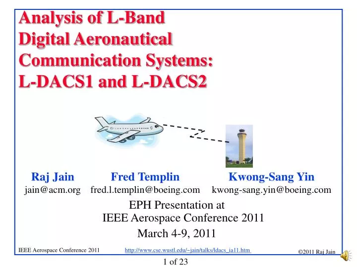
Analysis of L-Band Digital Aeronautical Communication Systems: L-DACS1 and L-DACS2. EPH Presentation at IEEE Aerospace Conference 2011 March 4-9, 2011. Overview. Evolution of Aeronautical Datalinks L-Band Digital Aeronautical Communication System (L-DACS1 and LDAC2) Functional Analysis

E N D
Analysis of L-Band Digital Aeronautical Communication Systems: L-DACS1 and L-DACS2 EPH Presentation atIEEE Aerospace Conference 2011 March 4-9, 2011
Overview • Evolution of Aeronautical Datalinks • L-Band Digital Aeronautical Communication System (L-DACS1 and LDAC2) • Functional Analysis • Interference Analysis • Performance Analysis
Evolution of Aeronautical Datalinks P34 L-DACS1 B-VHS B-AMC OFDM WiMAX UAT GSM E-TDMA AMACS L-DACS2 TDM ACARS VDL2 VDL4 LDL 1190ES Past Present Future
Evolution of Aeronautical Datalinks (Cont) • ACARS: Aircraft Communications Addressing and Reporting System. Developed in 1978. VHFand HF. Analog Radio • VDL2: Digital link. In all aircrafts in Europe. 1994. VHS. • VDL4: Added Aircraft-to-Aircraft. 2001. Limited deployment • LDL: L-Band Digital Link. TDMA like GSM. • E-TDMA: Extended TDMA. Hughes 1998. Multi-QoS • AMACS: All purpose Multichannel Aviation Communication System. 2007. L-Band. Like GSM and E-TDMA. • UAT: 981 MHz. 2002. One 16B or 32B message/aircraft/sec • P34: EIA/TIA Project 34 for public safety radio. Covers 187.5 km. L-Band. • B-VHS: MC-CDMA (OFDMA+CDMA). VHF. TDD. • B-AMC: Broadband Aeronautical Multicarrier System. OFDMA. B-VHS in L-Band.
L-DACS: Common Features • L-band Digital Aeronautical Communications System • Type 1 and Type 2 • Both designed for Airplane-to-ground station communications • Airplane-to-airplane in future extensions • Range: 200 nautical miles (nm) (1 nm =1 min latitude along meridian = 1.852 km =1.15 mile) • Motion: 600 knots = 600 nm/h = Mach 1 at 25000 ft • Capacity: 200 aircrafts • Workload: 4.8 kbps Voice+Data • All safety-related services • Data=Departure clearance, digital airport terminal information, Oceanic clearance datalink service
Issue 1: Modulation and Multiplexing • Modulation: • Single Carrier • Multi-carrier • Multiplexing: • Time division • Frequency division • Code division • Orthogonal Frequency Division
L-DACS1 • OFDMA: Similar to WiMAX • Multi-carrier: 50 carriers 9.76 kHz apart • Use two channels of 498 kHz each
L-DACS2 • Based on GSM • GSM PHY, AMACS MAC, UAT Frame Structure • Uses Gaussian Minimum Shift Keying (GMSK) modulation as in GSM • GSM works at 900, 1800, 1900 MHz Þ L-DACS2 is in lower L-band close to 900MHz • Tested concept • Price benefit of GSM components • Uses basic GSM not, later enhanced versions like EDGE, GPRS, …These can be added later. Ref: http://en.wikipedia.org/wiki/Gaussian_Minimum_Shift_Keying#Gaussian_minimum-shift_keying
Single vs. Multi Carrier • WiMAX, 11a/g/n use OFDM • Advantages of OFDM: • Graceful degradation if excess delay • Robustness against frequency selective burst errors • Allows adaptive modulation and coding of subcarriers • Robust against narrowband interference (affecting only some subcarriers) • Allows pilot subcarriers for channel estimation
9.76 kHz L-DACS1: OFDM Parameters • Subcarrier spacing: 9.76 kHz = Similar to WiMAX • Guard Time Tg = 17.6 ms = 5.28 km 17.6 ms
f f f f L-DACS1 Design Decisions • Large number of carriers Þ Reduced subcarrier spacing Þ Increased inter-carrier interference due to Doppler spread • Doppler causes carrier frequency shift: • WiMAX use 10 kHz spacing • Long Term Evolution (LTE) uses 15 kHz spacing to meet faster mobility 10 kHz spacing 20 kHz spacing
Multipath t t L-DACS1 Design Decisions • Multipath causes symbols to expand: • Guard time duration Tg (Cyclic prefix) is designed to overcome this delay spread. • 17.6 ms = 5.8 km path differential in L-DACS1 • LTE is designed with two CP lengths of 4.7 ms, 16.7 ms, and 33.3 ms (1.4km, 5 km, 10 km). t t
Base Subscriber Issue 2: Duplexing (TDD vs. FDD) • L-DACS1 is FDD, L-DACS2 is TDD. • Duplex = Bi-Directional Communication • Frequency division duplexing (FDD) (Full-Duplex) • Time division duplex (TDD): Half-duplex • Most WiMAX/LTE deployments will use TDD. • Allows more flexible sharing of DL/UL data rateGood for data • Does not require paired spectrum • Easy channel estimation Þ Simpler transceiver design • Con: All neighboring BS should synchronize Frequency 1 Base Base Subscriber Subscriber Frequency 2
Duplexing (cont) • L-DACS1 FDD selection seems to be primarily because 1 MHz contiguous spectrum may not be available in L-band. • Possible solution: Carrier-bonding used in the WiMAX v2 and in LTE
L-Band Spectrum Usage 969 1008 1053 1065 1113 1213 • L-DACS1 Þ 2x498.5 kHz FL in 985.5-1008.5MHz, RL in 1048.5-1071.5MHz, Duplex spacing 63 MHz • L-DACS2 Þ One 200 kHz channel in lower L-Band 960-975 MHz JTIDS JTIDS JTIDS (MIDS) UAT GSM DME DME DME Galileo/GPSDME SSR SSR Freq 960 978 1025 1035 1085 1095 1150 1164 1213 L-DACS2 L-DACS1 FL L-DACS1 RL DME=Distance Measuring Equipment JTIDS=Joint Tactical Information Distribution System MIDS=Multifunction Information Distribution System SSR=Secondary Surveillance Radar GSM=Global System for Mobile Communications
Issue 3: Interference Interfering Technologies: • Distance Measurement Equipment (DME) • Universal Access Transceiver (UAT) • 1090 Extended Squitter (ES) • Secondary Surveillance Radar (SSR) • Joint Tactical Information Distribution System (JTIDS) • Groupe Speciale Mobile (GSM) • Geostationary Navigation Satellite System (GNSS)
L - DACS A S DME XMTR Power 5 8.5 dBm Path lo ss - 3 5 dB Net Interference 2 3.5 dBm DME • Distance Measuring Equipment • Ground DME markers transmit 1kW to 10 kW EIRP. • Aircraft DME transmits 700W = 58.5 dBm • Worst case is Aircraft DME to Aircraft L-DACS • Same side of the aircraft or small aircrafts Þ Even 35 dB isolation results in +23.5 dBm • Need to design coordination
GSM Interference • Maximum allowed EIRP 62 dBm • 43 dB power + 19 dBi Antenna gain • 37 dB power + 25 dBi Antenna gain • -80 dBc power at 6 MHz from the carrier • GSM Interference: • L-DACS1 = -22dBm • L-DACS2= -10.8 dBm (L-DACS2 uses a band close to GSM)
Performance Requirements • Peak Instantaneous Aircrafts Counts (PIACs): APT = AirportTMA = Terminal Maneuvering area ENR = En route ORP = Oceanic/Remote/Polar AOA = Autonomous Operations Area Ref: Communications Operating Concepts and Requirements (COCR) V2
Performance Reqs (cont) • Maximum Airspeed in Knots True Air Speed (KTAS) • Most stringent capacity requirements in kbps: • Phase 2 begins in 2020. Requirements seem too low.
Data Rate • L-DACS1: QPSK1/2 - 64-QAM 3/4 Þ FL (303-1373 kbps)+ RL (220-1038 kbps) using 1 MHzÞ Spectral efficiency = 0.5 to 2.4 bps/Hz • L-DACS2: 270.833 kbps (FL+RL) using 200 kHzÞ Spectral efficiency = 1.3 bps/Hz(Applies only for GSM cell sizes)Signal to noise ratio decreases by the 2nd to 4th power of distance
Summary 1. L-DACS1 with OFDM is more scalable than L-DACS2 with single carrier modulation. 2. L-DACS1 also has better spectral efficiency because it can use adaptive modulation and coding (QPSK through 64 QAM). 3. Multi-carrier design of L-DACS1 is also more flexible in terms of spectrum placement. 4. Multi-carrier design of L-DACS1 is also more suitable for interference avoidance and co-existence than L-DACS2. 5. The TDD design of L-DACS2 is better suited for asymmetric data traffic than FDD design of L-DACS1. 6. The cyclic prefix and subcarrier spacing of L-DACS1 need to be analyzed to check if it will work at aircraft speeds. 7. GSM900 stations may cause significant interference with the L-DACS systems. Again L-DACS2 is more susceptible to such interference.
Related Papers and Biography • Raj Jain, Fred L. Templin, "Datalink for Unmanned Aircraft Systems: Requirements, Challenges and Design Ideas," AIAA Infotec@Aerospace Conference, Saint Louis, MO, March 2011, http://www1.cse.wustl.edu/~jain/papers/uas_dl.htm • Biography: Raj Jain is a Fellow of IEEE, a Fellow of ACM, a winner of ACM SIGCOMM Test of Time award, CDAC-ACCS Foundation Award 2009, Hind Rattan 2011 award, and ranks among the top 50 in Citeseer's list of Most Cited Authors in Computer Science. Dr. Jain is currently a Professor of Computer Science and Engineering at Washington University in St. Louis. Previously, he was one of the Co-founders of Nayna Networks, Inc - a next generation telecommunications systems company in San Jose, CA. He was a Senior Consulting Engineer at Digital Equipment Corporation in Littleton, Mass and then a professor of Computer and Information Sciences at Ohio State University in Columbus, Ohio. He is the author of ``Art of Computer Systems Performance Analysis,'' which won the 1991 ``Best-Advanced How-to Book, Systems'' award from Computer Press Association. His fourth book entitled " High-Performance TCP/IP: Concepts, Issues, and Solutions," was published by Prentice Hall in November 2003. He has recently co-edited "Quality of Service Architectures for Wireless Networks: Performance Metrics and Management," published in April 2010. Further information about Dr. Jain including all his publications can be found at http://www.cse.wustl.edu/~jain/index.html. jain@acm.org