Download
1 / 32
320 likes | 496 Views
Spherical Microwave Confinement. for the preliminary exam November 15, 2007 Bill Robinson. History. February 1995: Scientific American article on sonoluminescence and fusion got me started looking for exotic energy sources

E N D
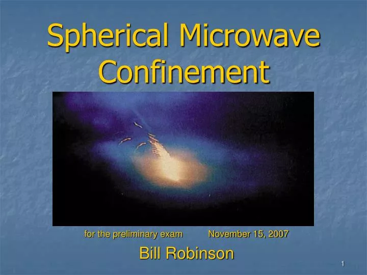
Spherical Microwave Confinement for the preliminary exam November 15, 2007 Bill Robinson
History • February 1995: Scientific American article on sonoluminescence and fusion got me started looking for exotic energy sources • 1996-99; investigated various cold fusion ideas, usually shock waves through hydride aerosols; gave up for lots of reasons • July 2000; started investigating idea of helical antennas in a sphere—and thought of coming to NCSU for physics • 2003; started interest in Ball Lightning (BL) • 2004; began grad school in hopes of building a reactor
More History • 2004-2006; went through large number of possible designs with this geometry (including Inertial Electrostatic Confinement [IEC]); ended up with magnetic SMC theory, BL on the side, formal papers • August 2006; started construction in 102-A Research II with Dr. Aspnes as advisor • Spring 2007; obvious that magnets are beyond my capacity in cost, manpower, time; found flaws in theory; concentrating on BL and SMC with no magnets • September 2007; first plasma • October 13 2007; back to SMC as IEC idea
SMC Reactor Design • 20 helical antennas for 2.45 GHz circularly polarized RF, 1 wavelength long, 4 ½ turns; aluminum sphere is groundplane at 4th zero of j1 = sin kr/(kr)2 – cos kr/kr (TE) • 20 magnetrons (1kW each) fire from cap bank (6kV to 4kV), ~1/10 sec • Each hemisphere mounted on independent framework on casters • 2 windows 2” diameter • Polar pipes (1 ¼”) for access, gas in/out, probes, sparker, fiberoptic • Can accommodate either hemispherical magnets or neutron shields 1 ½ inches off of surface, totally enclosing the sphere
A Tour of the Lab II Back of control panel and upper capacitor bank Baffles keep the ‘trons from going KERPOW From 5 magnetrons to coax Distributing power to the ‘trons
Video Stills Early shot; 3 torr, sparker loaded with flour and graphite; 30 fps; sparker should be delayed to have maximum during microwave discharge (is now!) 1) Sparker explodes aerosol 2) Magnetrons start breakdown 3) One of 3 frames, hot plasma 4) Winding down, helix cores last to cool
Abstract for Ball Lightning Research • By experimenting with a variety of targets, gases, and pressures, the objective is to create an analog to natural ball lightning (BL), discover optimal conditions more favorable than atmospheric, and investigate the anomaly • The spherical aluminum chamber confines the gas and aerosol at a wide range of pressures • A strong pulse of circularly polarized microwaves from all directions hits vaporized organic material • As natural BL emits microwaves, the BL should resonate in the chamber and move to the center • Any microwaves emitted can be gathered by the antennas and the power rectified to DC with high efficiency • A wide range of measurements and analysis would be possible for the first time, instead of just field reports, leading to theory of BL and reactor design
Abstract for SMC-IEC Research • Using the same geometry as for BL, with addition of bias rings at the antenna bases, waves of electrons flow into the center and cause a virtual cathode at the center, to which ions flow • As long as electrons are turned back before collision with the antennas, the result is gridless IEC with the potential for neutron production and possibly fusion power
Ball Lightning • We KNOW it does exist, unlike other exotic schemes. Ideal power source when harnessed • Extreme BL (EBL) has unmatched energy density (109 J/m3), beyond any chemistry from energy/molecule; no neutrons or gammas • EBL emits high levels of microwaves which are easily rectified (90+% efficiency) to DC • Hardly likely that Nature gives optimum conditions, but does give possible conditions • Can be made with common materials. Fuel likely to be abundant; best fuel unknown • Key is to take field observations at face value when possible without modification to fit preconceptions
Mysteries of BL: confinement • Typical lifetime is 10 sec (range 1 to 150 sec typically) instead of microseconds to cool, recombine • Neutral buoyancy; tends to hover over ground and can move upwind instead of rising • Can’t have separation of charges sustained in conductor, thus no E • B requires current which would need superconducting loop; plasmas have finite resistance. Density is too high for B confinement due to high collision rate >> gyrofrequency (density is atmospheric). • Neutrals may be confined since no cooling from convection, and “pop” on collapse evidence for internal pressure >> partial pressure of ionized fraction. No known mechanism for that. Would be ~15 atm! • If neutrals not confined, then plasmoid should cool and collapse in < 1 ms; would help explain BL moving upwind (but leaves most of the mystery)
More Mysteries of BL • Power output of BL not associated with cooling or reduction in size • Energy flows out continuously from visible light (recombination), RF (static recorded), sometimes heat • Energy out on explosion can include microwaves; unknown origin. Evidence from cooked meat, hot water • Total energy can be >> initial input especially when not generated by linear lightning, and energy is generated during lifetime of BL; evidence of anomalous sustaining reaction • Most powerful recorded BL formed underwater off coast of Japan
Using the reactor for BL • Magnetron cap bank charged mostly by an oven • Sparker (2kV) throws hot organic material into center • Microwaves hit and react with hot aerosol and fill gas for 50 to 130 ms as capacitor bank goes from 6000 to 4000 V, ~1000 J energy • Current equipment only goes down to 3 torr and cannot withstand positive internal pressure required to explore full range of conditions • After upgrade with flange, new antenna feedthroughs, and turbo pump, can do much lower pressures and over atmospheric • May use baffles, especially for higher pressures; requires seed plasma to absorb microwaves, otherwise can damage magnetrons; no problem now at 3 torr with baffles. Mysterious malfunction at 1 atm • Recently added Teflon shields at base of antennas to avoid breakdown, damage • If successful there is potential for explosive dissolution • For low pressures can use biasing rings at antenna bases (-6 kV to start with, described in next section)
How to make BL; a Best Guess • Take field evidence seriously; smell, aerosol, microwave damage, environment where formed • Smell indicates rotten egg (hydrogen sulfide) and ozone. O3 ubiquitous with sparks so may not be useful indicator • Solids required for aerosol formation; only solids in air are biological (birds, bats, bugs), so tests will use organic fuel for sparker • Closest atmospheric lab plasmas to BL are microwave discharges; must measure plasmoid duration after microwave power input stops • If BL puts out microwaves, makes sense to put in a potentially resonant chamber where it will tend towards the center • Should get it started with pulse of extreme conditions
How This Is New for BL Synthesis • Since microwaves come out of BL, makes sense to try making BL with a pulse of microwaves • Can expect BL to resonate in a spherical metal shell and tend to float in center; not tried before • Circularly polarized RF keeps constant magnitude fields; not tried before • Helical antennas in both rotations will receive all radiation efficiently regardless of direction • Chamber controls gas pressure and species, protects from explosions and BL microwaves • Sparker allows controlled introduction of aerosol
BL Diagnostics • Easy one is most important; does it last after power cuts off? Must have accurate measure of when microwave input stops • Currently have video at 30 fps; would like higher speeds, shielded from EMF • Will set up computer for data acquisition • By using coax relay can divert antenna for outgoing power after magnetrons stop, rectify and measure DC voltage to find microwave output. More ideal setup would have hybrid couplers but too expensive now • Can insert emissive probe along polar axis to find plasma potential regardless of electron drift [1] • Spectrometer probably via fiberoptic; need to borrow one! (From NE?) • Need good leak testing to improve vacuum • Gas analysis before and after pulse to detect reactants and products; gear available in lab
HOWEVER! • Making BL in this reactor is a long shot • Next; an explanation of a way of using this same geometry with minor changes at low pressures for Electron Accelerated Inertial Electrostatic Confinement (EXL IEC) without grids for conventional fusion reactions (D-D, D-T, proton-B11) • Unlike BL, the physics is known; critical point is to reverse electrons by near-field RF and inward-flowing electron waves before they reach the antennas, instead of requiring transit through grids • If this is correct, the existing hardware could produce large numbers of neutrons. The concept might be developed for power generation in larger and more efficient reactors
Inertial Electrostatic Confinement (Ref. 2)
IEC single potential well [3] Fig. 2: Single potential well structure. The minimum normalized potential, Ymin, coincides with the core potential, Ycore = Y(r = 0). The fractional well depth, FWD is defined as FWD = 1-Ymin.
IEC double potential well [3] Fig. 3: Double potential well structure. The double well depth (DWD) is Ypeak – Ymin. Here, Ypeak coincides with Ycore.
Existing IEC • Large increase of plasma density in potential wells, fosters high rate of reaction there; BUT net reaction rate ~ 1/pressure • IEC with grids cannot (yet) go above Q~10-5 • Big advantages: no B fields, easy high T, simple geometry, some fusion does occur at center and in mantle (zone between grids) • High T makes advanced fuels tempting but elusive so far • IEC operates at too low density for power reactor (need ~1021 m-3 in sizable volume) [5] • IEC is the cheapest way to fusion by a very large factor; reactors are mostly vacuum, thus low mass. • Existing grid reactor can be a practical, portable, simple neutron source (like the STAR reactor), but not efficient enough yet for sub-critical fission or large-scale transmutation. Maximum so far; 2x10¹⁰ neutrons/sec by Hirsch in the ’60s [6] and Nebel in late ’90s • Other attempts for either gridless IEC (Bussard) or to protect grids magnetically from collision have failed
Some recent experiments Richard Nebel’s Los Alamos Triple-gridded POPS IEC 1010 n/s, $500 k, 25 kW [4] Hitachi IEC, Japan, 7 x 10⁷ n/s
Unavoidable Loss Problems in grid IEC • Collisions with grids; Pgridloss/Pfusion > 3000; particle paths MUST cross grids to be confined [5] • Ion upscatter and energetic tail loss time ~10-3 fusion rate • Ion neutral capture and escape from potential well • Fusion reaction products escape, do not heat plasma (direct energy conversion probably won’t work) [8] • Ion collisions increase angular momentum and throw ions out of dense center region (may not be so bad, double wells can work) • No way to keep plasma non-thermal; collision x-section >> fusion x-section by factor of at least 105 • Bremsstrahlung same or worse as other reactors, makes advanced non-neutronic fuels probablyimpractical (fuel touted as ideal for IEC) • Both ion and electron loss times << fusion time
Critical IEC Scaling Problem: 1/n • As density drops, longer mean free path, more acceleration between grids, higher energy, increased <sv>, fewer ion-neutral collisions, tighter focus at center, more head-on collisions. [9] • Thus fusion reactions scale as 1/n instead of n2. IEC reactors operate at very high vacuum << fusion reactor range (1021) • Might not be true of SMC since mfp of runaway electrons are long due to velocity; acceleration from microwaves not grids; less focus anyway
Critical IEC scaling problem; Power ~ 1/a • a = radius of spherical active zone, q = total charge, fa = potential at r = a, ne and ni are average densities in the active zone, P = power from fusion • For grid IEC, q = |ne – ni| ~ ni • fa~ q/a ~ ni a3/a2 = ni a2 • Since fa is within a small range, ni ~ 1/a2 • P ~ ni2 *Volume, so P ~ 1/a • Probably NOT true for SMC since source of ions, electrons, and charge balance is not the same as for grids; q is not ~ ni • Proof of this is the use of ion or electron beams to alter the charge/density relationship in grid IEC to increase P • Result is IEC devices are very small (a few inches) and cannot scale up while SMC probably can
Antennas as e- accelerators • Antennas are insulated with ceramic and do not short out to plasma • Will apply -6 kV (or more) bias to base rings, 4” diameter, 1” from wall. Next reactor could put (+) bias on antennas • Microwaves cause breakdown starting in core, rapidly saturates to critical density (opaque plasma) • Electron cascade bunches in waves and flows toward center; same process turns back electrons from center (thermalized after crossing reactor core) • Uncoordinated antenna phases now; may be better in phase for inwards-moving spherical waves • Existing rig; ~5 x10⁸ e/cycle at ~25 keV (~0.2 amp) assuming delivering 5 kW to waves from microwaves (efficiency of 0.25) • Bias on base rings limited to no more than electron wave energy ~ virtual cathode potential; 10 kV for D-T reactor, 50 kV for D-D • Ions do not bunch in waves, follow e- inwards; qi(t)= <-qe(t-d)> • Inner charge during microwave increase; qtotal = qi - qe = - d <dqe/dt> (qe = # inner electrons) • For each 5 microseconds ion delay, can create 1 kV potential if low electron loss
Periodically Oscillating Plasma Sphere (POPS) Uses RF modulation of grids and emitters to oscillate the potential well in resonance with the orbital frequency of the ions to extend life of virtual cathode (a) Temporal evolution of plasma potential at the center of the virtual cathode with and without rf modulation. (b) Delay in the virtual cathode destruction due to rf modulation as a function of modulation frequency. (Reproduced from Ref. 4.) This is for just a few hundred volts and 10-6 torr
POPS & SMC? • POPS in grid IEC cannot scale to a reactor since • With rvc = virtual cathode radius, fo = potential well depth; note change in radius and compression ratio • Resonant frequency: • At fusion reactor conditions, 10-30 MHz (D-D); milder plasmas down to 1 MHz • Works by throwing a few ions out of potential well. Might use by RF imposed on bias grid or injected beams of e- or ions • Grid IEC needs addition of electrons at center to reduce ion space charge and allow compression, may also in SMC
Magnetic SMC: a possible future addition • Two hemispherical coils, counter-rotating • Uses cylindrical cusp to make electron cyclotron resonance (ECR) on spheroidal B isosurface at 875 gauss • Could help make plasma transparent outside plasmoid • Would heat electrons at ECR surface efficiently and selectively • reactor is constructed to accommodate the coils • Expensive and uses a lot of power if not superconducting • Could funnel reaction products out poles and equator for direct energy conversion Arrows are B field; center circle is plasmoid surface; outer circle is magnet coil
Magnetic SMC Coil windings in amp-turns for test reactor, one hemisphere (other hemisphere is negative of this) Tickmarks are meters; contours are B field magnitudes; dark circle is 875 gauss (ECR); outer circle is magnet; next circle in is pressure wall; dotted circle is inner end of antennas
Current and Future Research • THEORY; Ion heating; magnetrons are a few MHz out of phase, causes Landau damping [8] • Shock dynamics, if they apply, with antennas in phase or random (current setup is random); compression, heating • Confinement mechanism for electrons in SMC-IEC (no BL theory yet) • HARDWARE; Diagnostic tools are first priority; computer DAQ, plasma probes, spectrometer, gas analysis, and detectors for x-rays, gammas, neutrons, alphas • Upgrade of vacuum system for lower pressures and secure use of H2S for BL, or D2 and boranes for SMC • Installation of bias rings at antenna bases, -6 kV for now • GOALS; BL creation then reactor design, or SMC to scale up for D-D or D-T reactor, sub-critical fission, etc. • FUNDING! And a way to continue doing this after graduation—here if possible; post-doc?
References • 1) A. Siebenforcher, Rev. Sci. Instrum. 67(3), March 1996 • 2) Tom Ligon, Infinite Energy Issue 30, 2000 • 3) IEC thesis by Ryan Meyer, U. of Missouri-Columbia December 2007 • 4) J. Park, R.A. Nebel, S. Stange, Phys. Plasmas 12, 056315 (2005) • 5) ”A general critique of intertial-electrostatic confinement fusion systems”, Todd Rider, Phys. Plasmas 2 (6), June 1995 • 6) R. L. Hirsch, J. Appl. Physics 38, 4522 (1967) • 7) M. Rosenbluth, F. Hinton, Plasma Phys. Control. Fusion 36 (1994) 1255-1268 • 8) F. Chen, Plasma Physics and Controlled Fusion, 1984 • 9) “Development of a High Fluence Neutron Source for Nondestructive Characterization of Nuclear Waste”, M. Pickrell, LANL Technical Report (1999) • M. Bourham, class notes • Many BL articles in Nature over the last 80 years • Personal interviews with BL witnesses and their relatives (including Dr. Hallen) www.billrobinsonmusic.com/Physics for pictures, papers, latest news