Download
1 / 53
530 likes | 662 Views
Chapter 03 Spread Spectrum Technologies. Faculty of Computer Sciense and Engineering. Objectives.

E N D
Chapter 03Spread Spectrum Technologies Faculty of Computer Sciense and Engineering
Objectives • Comprehend the differences between, and explain the different types of spread spectrum technologies and how they relate to the IEEE 802.11 standard’s PHY clauses: FHSS, DSSS, HR/DSSS, ERP, and OFDM • Identify the underlying concepts of how spread spectrum technology works: Modulation and Coding • Identify and apply the concepts which make up the functionality of spread spectrum technology • - Colocation • - Channel Centers and Widths • - Carrier Frequencies • - Dwell Time and Hop Time • - Throughput Versus Data Rate • - Bandwidth • - Communication Resilience
The OSI Model The OSI was developed by the ISO. ISO: International Organization for Standardization OSI stands for Open Systems Interconnection. The OSI is actually divided into two major portions: the abstract reference model and the specific set of protocols. The more impactful of the two has been the abstract reference model, which is called the seven-layer model, because of its use of seven layers of communications, and is the portion of OSI referenced by terms like OSI model or OSI reference model.
The OSI Model Briefly Explained • Each layer is defined by a descriptive term that helps in understanding the actions and the technology that is used within that layer. • - Layer 7: Application • - Layer 6: Presentation • - Layer 5: Session • - Layer 4: Transport • - Layer 3: Network • - Layer 2: Data Link • - Layer 1: Physical • When an application communicates across the network—wired or wireless—it is said to send the network communication down from Layer 7 through Layer 1 and then the receiving application will retrieve the data as it passes up from Layer 1 through Layer 7.
Spread Spectrum Technologies and IEEE 802.11 Standards
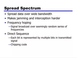
Spread Spectrum Versus Narrowband Technology Narrowbandwireless communications can be defined as wireless communications using a single frequency center with no redundancy to communicate information at high power levels chosen to overpower interference in that frequency band. Spread spectrumwireless communications can be defined as wireless communications using a range of frequencies to communicate information at low power levels. Spread spectrum has also been defined as a wireless communications technology that uses more bandwidth than is required to deliver information. Spread spectrum also uses low power and can do so because all interference does not need to be overcome, due to the redundancy and/or error correction.
Frequency Hopping Spread Spectrum (FHSS) Provides a 1 or 2 Mbps data rate using the 2.4 GHz ISM band. Within North America, FHSS uses seventy-nine 1 MHz channels Centered on every 1 MHz from 2.400 GHz to 2.4835 GHz. FHSS systems use a small frequency bandwidth within the 79 MHz allocated, to communicate and then hop to another frequency and then another until a hopping pattern known as a hopping sequencehas been completed. When the hopping sequence is completed, it is then repeated, and this process continues until the information being communicated has been transferred. Additionally, a dwell timeis specified, which determines how long each frequency will be utilized before hopping to the next in the hopping sequence.
FHSS FHSS provides for resistance to interference through the use of small frequency bandwidths and transfer algorithms that accommodate for errors in transmissions. For example, if data is communicated on a particular frequency and interference is encountered, that data will simply be retransmitted once the radios move on to the next frequency in the hopping sequence. This will reduce the actual data throughput of the system, but this resilience provides for reasonably stable communications.
Direct Sequence Spread Spectrum (DSSS) Supports speeds of 1 or 2 Mbps just like FHSS systems. Later amendments to the IEEE 802.11 standard provided for higher data rates and accomplished this through a different implementation of DSSS. The IEEE standards divide the DSSS Physical layer into two components: the Physical Layer Convergence Procedure (PLCP) and the Physical Medium Dependent (PMD). The PMD defines that actual method used to transmit data between two wireless devices. The PLCP acts as an abstraction layer between the PMD and the Medium Access Control (MAC) services.
DSSS DSSS systems are also resistant to narrowband interference like FHSS systems. Because DSSS systems use narrow bandwidths and do not hop from one frequency to another, they may be more susceptible to interference than FHSS systems. If a narrowband signal is broadcast on the same frequency as the center channel frequency for DSSS WLAN, it will cause continual interference. If a similar situation should occur with a FHSS system, it would only cause interference when the system hopped to that frequency. In most cases, the narrowband interference will be benign, since it only takes out a few copies of the bits (DSSS transmits redundant copies of the data). As long as one copy gets through, it is as though the interference does not exist because there is no loss of information.
High-rate DSSS (HR/DSSS) HR/DSSSis the PHY defined in the IEEE 802.11b-1999 amendment. HR/DSSS PHY is backward compatible with IEEE 802.11 DSSS equipment, but it is not compatible with IEEE 802.11 FHSS equipment. The primary objective of TGb (task group b) was to provide higher data rates within the 2.4 GHZ and compatibility with modulations used by DSSS PHY. This was accomplished using the same frequency range as used by DSSS. Using complementary code keying (CCK), TGb was able to achieve data rates of 5.5 and 11 Mpbs. This resulted in a collection of data rates 1, 2, 5.5, 11 Mbps.
Orthogonal Frequency Division Multiplexing (OFDM) OFDM is specified in the 802.11a and 802.11g amendments and can transmit at speeds of up to 54 Mbps. OFDM is not a spread spectrum technology, even though it has similar properties to spread spectrum, such as low transmit power and using more bandwidth than is required to transmit data. OFDM actually transmits across 52 separate, closely and precisely spaced frequencies, often referred to as subcarriers
Convolution Coding In order to make OFDM more resistant to narrowband interference, a form of error correction known as convolution coding is performed. Convolution coding is not part of OFDM but rather part of 802.11a and 802.11g. It is a forward error correction (FEC) that allows the receiving system to detect and repair corrupted bits. There are many levels of convolution coding. Convolution coding uses a ratio between the bits transmitted vs. the bits encoded to provide these different levels. The lower the ratio, the less resistant the signal is to interference and greater the data rate will be.
Modulation Modulationis the process of manipulating a carrier signal so that it can represent intelligent information. There are two kinds of modulation: digital and analog modulation. An RF signal can be modulated by manipulating the frequency, phase, or amplitude. Amplitude modulation is often affected by interference. WLAN technologies use different kinds of phase modulation. Frequency modulation is also used, though it is less common today. RF signals are modulated so that they can represent these 0s and 1s. As long as a 0 or 1 can be represented, any computer information can be transferred on the signal.
The sending alert—a preamble —is sent first as 180-degree phase shifts from 0 to 1 and then back to 0. Next, two 0s are sent, so there is no phase shift, and these two 0s are followed by four 1s, indicated by a phase shift at millisecond 6. Finally, another phase shift at millisecond 10 indicates that the transmission should now represent a 0, and the two 0s end the eight-bit binary number that was transmitted.
FHSS Modulation FHSS systems, which meet the specifications of the IEEE 802.11 standard, use a form of modulation known as Gaussian frequency shift keying (GFSK). Both two-level and four-level GFSK (2GFSK and 4GFSK) are supported by the standard for 1 and 2 Mbps data rates, respectively. This modulation technique does use the frequency as the manipulated characteristic of the RF signal to impress data on the wave. GFSK uses either two frequencies (2GFSK) or four frequencies (4GFSK) to encode the information onto the signal.
Gaussian frequency shift keying (GFSK) 2GFSK 4GFSK
DSSS Modulation DSSS systems use differential phase shift keying (DPSK) to modulate information onto carrier signals. Like FSK, phase-shifting modulation schemes are resistant to interference because the phase is not usually impacted by interference. This first kind of DPSK used in DSSS systems, called differential binary phase shift keying (DBPSK), provides a data rate of 1 Mbps. DBPSK uses the term binary because a single entity (a phase shift) is used to encode information onto the signal. For example, if there is no phase shift, the information is a 0 bit, and if there is a 180-degree phase shift, the information is a 1 bit.
DSSS Modulation The second kind of modulation used in DSSS systems is differential quadrature phase shift keying (DQPSK). This phase-shifting technique uses four different shifts to represent four different values. Using a four-shift modulation scheme allows for faster data rates, and this is why DQPSK is used when communicating at 2 Mbps
HR/DSSS Modulation HR/DSSS uses a combination of DQPSK and complementary code keying (CCK) for modulation. Either four or eight bits are encoded in each symbol period. - Four bits are used for 5.5 Mbps communications. - Eight bits are used for 11 Mbps. In either case, two bits are always modulated using DQPSK, and the remaining bits are modulated using CCK.
OFDM Modulation OFDM systems, such as IEEE 802.11a and 802.11g, use different modulation techniques depending on the data rate. Modulations include DBPSK, DQPSK, 16-QAM, and 64-QAM. 16-QAM supports 16 possible phase shifts 64-QAM supports 64 possible phase shifts
FHSS Coding The only coding employed in FHSS systems is the hopping sequence
DSSS Coding Unlike FHSS systems, DSSS systems do encode the information to be transferred. Redundant information is added to the information to be transferred through a process known as processing gain. Each data bit is processed mathematically against a fixed-length binary number known as a pseudorandom number, or PN. The mathematical operation performed, called XOR’ing, results in a much larger amount of data than the original bit. The IEEE requires a processing gain of 11 for DSSS systems, which results in an 11 bit chunk of information for every single bit of actual data. The resulting 11 bit chunk is called a chip.
DSSS Coding The specific code that is used as a PN code is known as the Barker sequence or the chipping code. This code is equal to 10110111000 This means that the bit value of 0 is transmitted as 01001000111 and the bit value of 1 is transmitted as 10110111000. This encoding occurs before the data is modulated, the actual data is never modulated onto the carrier signal. Instead, the result of XOR’ing each signal bit against the Barker sequence is modulated. This result (11 chips) is also known as the Barker code. By transferring this calculated information (the chips) instead of the original bits, the standards make it possible to recover from interference problems.
HR/DSSS Coding CCK is used in HR/DSSS implementations such as 802.11b. CCK uses a PN code that results in a processing gain of 8 instead of 11. The second difference between CCK and Barker sequencing is that CCK uses different PN codes for different bit sequences. Whereas the Barker sequence is always 10110111000, the CCK 8-chip sequence is calculated according to the data being encoded. The data is encoded in 8-bit chunks at 11 Mbps and 4-bit chunks at 5.5 Mbps. There is a one-to-one relationship that exists between every possible 8 bits of actual data and the 8-chip sequence that is calculated to represent that data. Once the data is encoded with CCK, it is modulated onto the carrier signals, using DQPSK.
OFDM Coding OFDM systems support a type of coding known as convolution coding. Convolution coding is not actually part of OFDM but is an IEEE 802.11a/g – supported forward error correction mechanism that provides error correction to OFDM communications. Convolution coding adds extra information to the transmitted data that is comparable to the parity data used to provide fault tolerance in storage systems. If an OFDM subcarrier is experiencing interference, the receiving device can regenerate the original data using the parity-type information that has been added to the data before transmission.
Dwell Time FHSS systems include characteristics such as dwell time, hopping sequences, and hop time. These characteristics come together to make up how the FHSS system will function and the actual data throughput that will be available. The amount of time spent on a specific frequency in an FHSS hopping sequence is known as the dwell time. These channels, 1 MHz of bandwidth each, provide 79 optional frequencies on which to dwell for the specified length of the dwell time.
Hopping sequence The hopping sequence is the list of frequencies through which the FHSS system will hop according to the specified dwell time. The IEEE 802.11 standard, section 14.6.5, states that 1 MHz channels should be used. These channels exist between 2.402 and 2.480 GHz in the United States and most of Europe. Every station in a Basic Service Set must use the same hopping sequence. Every station must also store a table of all the hopping sequences that are used within the system. These hopping sequences must have a minimum hop size of 6 MHz in frequency. If the device is currently communicating on the 2.402 GHz frequency, it must hop to 2.408 GHz at the next hop at a minimum.
Hop Time The duration of time required to hop from one frequency in the hopping sequence to the next is called the hop time. Hop times are measured in microseconds (μs) and are commonly rated at 200–300 μs. The FCC specifies that a maximum dwell time of 400 ms per carrier frequency in any 30-second window must be enforced.
Carrier Frequencies, Channel Centers, and Widths FHSS FHSS systems use the frequency range from 2.402 to 2.480 GHz, providing 79 MHz of frequency space in the 2.4 GHz. The FHSS systems use hopping sequences across multiple carrier frequencies, and these carrier frequencies are also sometimes called channels. The carrier frequencies are 1 MHz wide in FHSSS systems. This means that every carrier frequency is centered on a channel from 2.402 to 2.480 GHz.
Carrier Frequencies, Channel Centers, and Widths DSSS The IEEE 802.11 standard calls for use of the 2.4 GHz ISM band ranging from 2.400 to 2.497 GHz. In the United States and Europe, the range from 2.4000 to 2.4835 GHz is specified as the total frequency space available. The DSSS channels are 22 MHz wide, and the center of each channel is spaced 5 MHz from the closest channels.
Carrier Frequencies, Channel Centers, and Widths OFDM: IEEE 802.11a and IEEE 802.11g both use OFDM modulation. The 5 GHz U-NII bands are used with IEEE 802.11a, and the 2.4 GHz ISM band is used with IEEE 802.11g. OFDM—IEEE 802.11a The frequency bands specified in the IEEE 802.11a standard are ■ 5.150–5.250 GHz—Lower U-NII Band ■ 5.250–5.350 GHz—Middle U-NII Band ■ 5.725–5.825 GHz—Upper U-NII Band These bands are each divided into four nonoverlapping channels for a total of 12 nonoverlapping channels available to IEEE 802.11a devices. OFDM uses subcarriers, so each of these channels will have 52 subcarriers that actually transmit the data.
OFDM—IEEE 802.11g Since the IEEE 802.11g standard calls for the use of the 2.4 GHz ISM band, the frequencies used for OFDM channels are different from those used in IEEE 802.11a. In fact, the OFDM (ERP-OFDM) implemented in IEEE 802.11g uses the same channels as HR/DSSS and DSSS implemented in IEEE 802.11b and IEEE 802.11, respectively. This is why an IEEE 802.11g–compliant access point or wireless router has the same channels available in the configuration screens as the older IEEE 802.11 and 802.11b devices.
Colocation Refers to the ability to place multiple devices in an environment so that they will cause little or no interference to each other. FHSS FHSS systems can be colocated by using hopping sequences that result in infrequent simultaneous channel usage. In other words, the hopping sequences will be arranged in such a way that there are very few times, if any, where two different service sets are trying to dwell on the same channel. The IEEE standard defines hopping sequences that will allow for multiple service sets to exist in a service area. These hopping sequences use patterns that are based on mathematical algorithms
Colocation DSSS The maximum number of nonoverlapping service sets that can be created using DSSS technology is three. The center channel frequencies must be spaced by 25 MHz in order to be considered nonoverlapping by the IEEE standards. The three nonoverlapping channels that can be used in the same service area simultaneously are 1, 6, and 11. OFDM IEEE 802.11g (ERP-OFDM) can use the same three nonoverlapping channels as DSSS systems and can provide a total of 162 Mbps. IEEE 802.11a can use all eight nonoverlapping channels in the lower and middle U-NII bands for an aggregate speed of 432 Mbps in a service area.