Download
1 / 44
480 likes | 669 Views
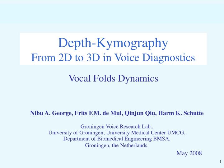
Depth-Kymography From 2D to 3D in Voice Diagnostics. Vocal Folds Dynamics. Nibu A. George, Frits F.M. de Mul, Qinjun Qiu, Harm K. Schutte Groningen Voice Research Lab., University of Groningen, University Medical Center UMCG, Department of Biomedical Engineering BMSA,

E N D
Depth-KymographyFrom 2D to 3D in Voice Diagnostics Vocal Folds Dynamics Nibu A. George, Frits F.M. de Mul, Qinjun Qiu, Harm K. Schutte Groningen Voice Research Lab., University of Groningen, University Medical Center UMCG, Department of Biomedical Engineering BMSA, Groningen, the Netherlands. May 2008
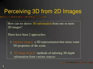
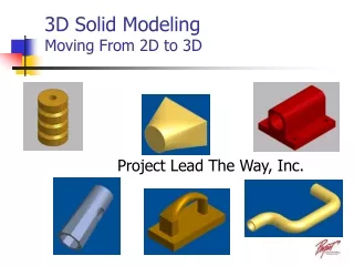
FirstVideo-kymography project: “Voice Diagnostics in a New Perspective” • Goal: To develop and apply a new type of video-camera to image Vocal Folds and their horizontal positions and movements in patients. • This (second) project: To measure vertical positions and movements of vocal folds. • Experimental: develop instrumentation • Numerical: develop simulation of dynamics • Develop method to compare measurements and simulations
glass fiber light cable mouth light source endoscope optical adapter camera microphone computer EGG glottis throat 2D-Videokymography system
Vocal Folds: top view 1,2: Left and right vocal fold 3: Blood vessel 4: Glottis: opening between folds, partly or completely closed during phonation Imaged line in Videokymography
time Vocal Folds: top view Videokymography: Imaged line as a function of time Glottis Blood vessel
Optical axis of Endoscope Camera system of Kymograph Vocal folds 2D-Videokymography system Glass fiber from light source Image of one camera line is recorded repeatedly. Shown: imaging of one point. NB. In this figure (and all following figures) the vocal folds are drawn after rotation over 900. (In reality the glottal midline is parallel to the endoscope axis).
Camera system of Kymograph Line triangulation Semi-transparent mirror Laser Cylindrical mirror Detector array Vocal folds top view Vocal folds (900 rotated) Videokymography system with 3D-extension Detector array might be combined with camera system.
Line triangulation Vocal folds top view Videokymography system with 3D-extension Laser beam mirror Detector array target
laserdriver laser projection channel high-speed camera endoscope camera control unit optical fiber vocal folds white light source Videokymography system with 3D-extension Resolution: 50 m (hor. & vert.) Nibu A George, Frits F M de Mul, Qingjun Qiu, Gerhard Rakhorst and Harm K Schutte, “Depth-Kymography: High-speed calibrated 3D imaging of human vocal fold vibration dynamics”, Phys. Med. Biol. 53, May 2008, 2667-77.
Videokymography system with 3D-extension • System characteristics • Laser :658 nm, 90 mW (on vocal folds: 14 mW) • Laser line on vocal folds :18 mm x 0.4 mm • Triangulation angle :7 o • Camera systems: • High-speed camera (Wolf) • 4000 fps, color, 256 x 256 pixels @ 13 x 13 m2 • Position-sensitive linear detector array (Hamamatsu) • 256 x 2 pixels @ 13 m x 1 mm.
Vocal Folds Dynamics one cycle Left:Modal Right:Falsetto At left side of each: Dotted region: solid lip Open region: mucosal lip time From: Hirano (1968)
time Conventional 2D - Kymography time
What do we want to see: time time 2D Kymography line with extra: vertical profile.
Nibu A George, Frits F M de Mul, Qingjun Qiu, Gerhard Rakhorst and Harm K Schutte, “Depth-Kymography: High-speed calibrated 3D imaging of human vocal fold vibration dynamics”, Phys. Med. Biol. 53, May 2008, 2667-77.
What do we want to see: time depth width 2D Kymography line with extra: vertical profile.
Awarded (for the novelty, significance and potential impact on future research)
Numerical simulations: Vocal Folds Dynamics • Goals: • To simulate the horizontal and vertical motions of the vocal folds, as functions of time • To directly compare measurements and simulations • Modeling: • Vocal folds modelled as two masses, • With horizontal and vertical freedom, • Connected by springs and dampers, • Driven by air pressures • Simulate (as functions of time): • Coordinates • Pressures • Flows
Numerical simulations: Vocal Folds Dynamics • Most important references: • Ishizaka, K. and Flanagan, J.L.,Synthesis of voiced sound from a two-mass model of the vocal cords, Bell Syst. Tech. Journ. 51, 1972, 1233-1267. • Titze, I.R.,The human vocal cords: A mathematical model I+II, Phonetica, 28, 1973, 129-170. • Koizumi, T., Taniguchi, S., Hiromitsu, S.,Two-mass models of the vocal cords for natural sounding voice synthesis, J. Acoust. Soc. Amer. 82, 1987, 1179-1192 + corrections
Schematic time cycle Modeling time From: Hirano (1968) Blocks may also have vertical freedom
y, flow x = spring and damper 2-masses model
tomouth y, flow expansion vocaltract x glottismidline glottis contraction trachea pressure tolungs
F open closure midline x x0 0 0 x0 x linear term (prop. to displacement) incl. non-linear term incl. closure term Spring forces: also for y x0,, y0 = position at rest
open closure F x x0 0 0 x0 x constant term ~ velocity also for y x0,, y0 = position at rest incl. closure term incl. singularity smoothing Damping forces(prop. to velocity)
y, flow x Pressures in x-direction Pressures in y-direction Forces from pressures Pressure forces F = Pressure P * exposed area A Pressures depend on actual coordinates
y, flow x Combined Model 6 System variables: for both masses: x- and y-positions, thicknesses d 4 Equations of motion ( x and y for both masses): 2 Additional constraining equations: 1. Conservation of total mass 2. y1 , y2 , d1and d2 connected => 4 Independent variables
y, flow x Combined Model • Other models: • Ishizaka & Flanagan: • Only x-dependence • Fixed depths ( d ) and widths ( w ) • Forces not in center-of-masses • Koizumi: • No wall connection for upper mass • Forces not in center-of-masses
y, flow P2,y x F1x F2x x1 0 x2 x10 0 x20 P2,x 2 F2y F1y x2(t) 0 x1 P1,x 1 x1 0 x2(t) F2y F1y x1(t) 0 x2 P1,y x2 0 x1(t) Pressure forces
vocal tract part n vocal tract part 1 vocal tract part 2 lungs trachea glottis mouth Rg Lg Rg = Rcontraction + Rmass1 + R1→2 + Rmass2 + Rexpansion Lg = Lcontr + Lmass1 + Lmass2 Electrical analogon for pressures and flows All resistances, compliances and inertias: expressions according to air flow in tubes with dynamic lengths and diameters. Static situation (DC): all inertia’s (L) = 0 and all compliances (C) = ∞. Vocal tract: components dependent on vowel characteristics ( 45 comp.)
A = cross-sectional area l = length R = flowresistance = f ( A,l,Ug ) L = flow inertia = f ( A,l ) y, flow x Ug 2 2 1 1 Glottis area Ug = flow [m3/s] Vg = dUg / dt P = pressure [Pa] P =Rexp.Ug expansion P = R2 .Ug + L2 . Vg glottis P = Rmid .Ug A P = R1 .Ug + L1 . Vg contraction P = Rcontr .Ug pressure
Calculations • Initial conditions: • Zero’s; build-up of Plungs at t > 0. • Stable (DC) situation. (*) Electrical analogon of coupled circuits: set of 2.(n+2) linear equations to solve (n = no. of vocal tract compartments) New circuit elements ( R, L, C ) New flows (*) New pressures and forces (+) 4 coupled non-linear equations of motion, with 2 additional constraining equations (total mass, and y-positions); iterative approach. New coordinates (+) no End time reached? Time step yes End
Masses (averages, amplitudes) in various models Models: (ABC) A = 1: Ishizaka/Flanagan 2: Koizumi 3: Combined B: lower mass C: upper mass B,C = 1: d & w var. 2: d var., w fixed 3: d & w fixed “ “Error bars” denote oscillation amplitudes
Coordinates (averages, amplitudes) in various models Models:(ABC) A = 1: Ishizaka/Flanagan, 2: Koizumi, 3: Combined B: lower mass; C: upper mass B,C = 1: d & w var.; 2: d var., w fixed; 3: d & w fixed “Error bars” denote oscillation amplitudes
Flows, pressures and frequencies in various models Models: (ABC) A = 1: Ishizaka/Flanagan, 2: Koizumi, 3: Combined B: lower mass; C: upper mass B,C = 1: d & w var.; 2: d var., w fixed; 3: d & w fixed Ref: model 333
Frequency peaks: intensity ratios in various models Models:(ABC) A = 1: Ishizaka/Flanagan, 2: Koizumi, 3: Combined B: lower mass; C: upper mass B,C = 1: d & w var.; 2: d var., w fixed; 3: d & w fixed Ref: model 333
Effects of different Vocal Tract Area Functions (VTAF’s). Mouth opening Top glottis Vocal Tract Area Functions (according to Story & Titze). Component length: 0.40 cm.
Effects of different Vocal Tract Area Functions (VTAF’s). Model 312. The variable values are relative to the values of VTAF no. /o/.
Effects of different Vocal Tract Area Functions (VTAF’s). Vowels /i/, /o/, /a/ (for components: ref. Story & Titze). /o/ /i/ /a/ Flow in mouth (time) Pressure in mouth (gray)andglottis (purple; shifted over 1/20 scale) (freq.)
Effects of different Vocal Tract Area Functions (VTAF’s). Vowels /i/, /o/, /a/ (for components: ref. Story & Titze). Pressure in mouth (gray) and glottis (purple; shifted over 1/20 scale) (freq.) /a/ /o/ /i/
Comparison of measurements and simulations Successive vertical cross sections of the simulations, during one vibration cycle. Curve: overlay of the corresponding depth-Kymographic measurement.
Conclusions so far: • 1. Laryngoscope for Depth-Kymography: • Design and developmentready • Successful tests with human subjects • 2. The program seems to be capable of simulating • the vocal fold dynamics: • In horizontal and vertical directions • With mass exchange between solid mass (lower) and mucosal mass (upper) • 3. Additional result: • Direct comparison between simulations and measurements. The end