Download
1 / 24
370 likes | 1.19k Views
master thesis presentation Development of an Atomic Force Microscope. author Jan W. Obrębski supervisors Eric S. Buice Jonathan D. Ellis Jo W. Spronck. AFM technology introduction.

E N D
master thesis presentationDevelopment of an Atomic Force Microscope author Jan W. Obrębski supervisors Eric S. Buice Jonathan D. Ellis Jo W. Spronck
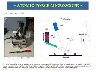
AFM technology introduction Yacoot A, Koenders L. topical review: Aspects of scanning force microscope probes and their effects on dimensional measurement. Journal of Physics. 2008 May; 41(10)
Assignment description • Design of an AFM vertical scanner • Surface topography measurement • System requirements
Scanner assembly piezoelectric actuator structural frame sensor mount bracket flexure capacitive sensor probe flexural stage capacitive sensor target AFM probe
Working principle stage actuation amplifier Abbé feedback (PI control) topography measurement topography input
Probe mount gold pad soldering pad silver line steel plate NANOSENSORS™, Rue Jaquet-Droz 1, Case Postale 216 CH-2002 Neuchatel, Switzerland
Flexure stage • Monolithic design • Al 7075 - T6 • Elastic guidance • Overconstrained • PZT preload • High f0 > 6 kHz • Low mass (6.6 g) • High PZT stiffness • Low deformation • Low actuation forces (5 N) Fpzt Metrology sensitive
ANSYS modal analysis 1st mode 5.2 - 6.8 kHz 2nd mode 7.85 kHz 3rd mode 7.9 kHz 1st cover mode 9 kHz
Capacitive sensor gap adjustment electrode wire pockets sensing electrode nominal gap 50 µm guard electrode target electrode integrated metrology frame
Squeeze film damping ANSYS, Green’s function Pressure distribution 2 vented edges Pressure distribution 4 vented edges Elastic deformation F = 0.1 N, b = 0, r = 0.4nm
Capacitive sensor electronics • AC transformer bridge • Implementation issues • Grounding loops elimination • Shielding
Calibration results 1 nm traceable uncertainty calibration Capacitive sensor : 2nd order fit Actuator open loop hysteresis
Frequency response analysis • Three methods used • Laser vibrometer • Multisine feed • Sine sweep • Capacitance sensing • PZT stiffness variation • Stiffening cover effect
Feedback controller • Based on ARX [10, 10, 3] system model • Digital Proportional Integral (PI) and notch filter, 100 kHz sampling • Robust design for loop gain variation • Piezoelectric hysteresis elimination (I)
Conclusions (1) • START: specifications • Concept, modelling, design • Stage, sensor,AFM probe, probe mount • Actuator, driving amplifier • PCB design • Manufacturing • Assembly • Integration
Conclusions (2) • Electronics implementation • Calibration • Frequency response • System identification • Feedback control
Conclusions (3) • END: working hardware • 2.5 kHz bandwidth • 2 nm uncertainty (1σ) • 13 µm steps • 2.8 nm resolution
DISCUSSION THANK YOU FOR YOUR ATTENTION!