Download
1 / 24
250 likes | 402 Views
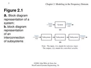
Lecture 1: UML Class Diagram. September 12, 2011. What is a Class Diagram?. A class diagram describes the types of objects in the system and the various kinds of static relationships that exist among them. A graphical representation of a static view on declarative static elements.

E N D
Lecture 1:UML Class Diagram September 12, 2011
What is a Class Diagram? • A class diagram describes the types of objects in the system and the various kinds of static relationships that exist among them. • A graphical representation of a static view on declarative static elements. • A central modeling technique that runs through nearly all object-oriented methods. • The richest notation in UML. UML Class Diagrams
Essential Elements of a UML Class Diagram • Class • Attributes • Operations • Relationships • Associations • Generalization • Dependency • Realization • Constraint Rules and Notes UML Class Diagrams
Classes in UML • A class is the description of a set of objects having similar attributes, operations, relationships and behavior. Class Name Attributes Operations UML Class Diagrams
Corresponding Java Class class Flight { int flightNumber; Date departureTime; Minutes flightDuration; public Date delayFlight(int numberOfMinutes); public Date getArrivalTime(); } UML Class Diagrams
Employee Department Company Associations • A semantic relationship between two or more classes that specifies connections among their instances. • A structural relationship, specifying that objects of one class are connected to objects of a second (possibly the same) class. • Example: “An Employee works for a department and the department belongs to a company” UML Class Diagrams
Associations (cont.) • An association between two classes indicates that objects at one end of an association “recognize” objects at the other end and may access to them. • This property will help us discover less trivial associations using interaction diagrams. UML Class Diagrams
Associations (cont.) Role name Association name instructor StaffMember Student 1..* instructs * Role Navigable (uni-directional) association Multiplicity * pre - requisites Courses 0..3 Reflexive association UML Class Diagrams
Associations (cont.) • To clarify its meaning, an association may be named. • The name is represented as a label placed midway along the association line. • Usually a verb or a verb phrase. • A role is an end of an association where it connects to a class. • May be named to indicate the role played by the class attached to the end of the association path. • Usually a noun or noun phrase • Mandatory for reflexive associations UML Class Diagrams
Associations (cont.) • Multiplicity • The number of instances of the class, next to which the multiplicity expression appears, that are referenced by a single instance of the class that is at the other end of the association path. • Indicates whether or not an association is mandatory. • Provides a lower and upper bound on the number of instances. UML Class Diagrams
Associations (cont.) • Multiplicity Indicators UML Class Diagrams
2..* 1..* Door Car House Aggregation • A special form of association that models a whole-part relationship between an aggregate (the whole) and its parts. • Models a “is a part-part of” relationship. Whole Part UML Class Diagrams
Aggregation (cont.) • Aggregation tests: • Is the phrase “part of” used to describe the relationship? • A door is “part of” a car • Are some operations on the whole automatically applied to its parts? • Move the car, move the door. • Are some attribute values propagated from the whole to all or some of its parts? • The car is blue, therefore the door is blue. • Is there an intrinsic asymmetry to the relationship where one class is subordinate to the other? • A door is part of a car. A car is not part of a door. UML Class Diagrams
Composition • A strong form of aggregation • The whole is the sole owner of its part. • The part object may belong to only one whole • Multiplicity on the whole side must be zero or one. • The life time of the part is dependent upon the whole. • The composite must manage the creation and destruction of its parts. Department University UML Class Diagrams
An abstract class Shape <<abstract>> Super Class Generalization relationship Sub Class Circle Generalization • Indicates that objects of the specialized class (subclass) are substitutable for objects of the generalized class (super-class). • “is kind of” relationship. {abstract} is a tagged value that indicates that the class is abstract. The name of an abstract class should be italicized UML Class Diagrams
Generalization • A sub-class inherits from its super-class • Attributes • Operations • Relationships • A sub-class may • Add attributes and operations • Add relationships • Refine (override) inherited operations • A generalization relationship may not be used to model interface implementation. UML Class Diagrams
Dependency • A dependency indicates a semantic relation between two or more classes in which a change in one may force changes in the other although there is no explicit association between them. • A stereotype may be used to denote the type of the dependency. Iterator <<friend>> Vector UML Class Diagrams
Realization • A realization relationship indicates that one class implements a behavior specified by another class (an interface or protocol). • An interface can be realized by many classes. • A class may realize many interfaces. LinkedList <<interface>>List UML Class Diagrams
id: long { value > 0 } Customer 1 * Order may be canceled { total < $50 } Constraint Rules and Notes • Constraints and notes annotate among other things associations, attributes, operations and classes. • Constraints are semantic restrictions noted as Boolean expressions. • UML offers many pre-defined constraints. Constraint Note UML Class Diagrams
Name UML Packages • A package is a general purpose grouping mechanism. • Can be used to group any UML element (e.g. use case, actors, classes, components and other packages. • Commonly used for specifying the logical distribution of classes. • A package does not necessarily translate into a physical sub-system. UML Class Diagrams
Logical Distribution of Classes • Emphasize the logical structure of the system (High level view) • Higher level of abstraction over classes. • Aids in administration and coordination of the development process. • Contributes to the scalability of the system. • Logical distribution of classes is inferred from the logical architecture of the system. UML Class Diagrams
A D E F G C B Packages and Class Diagrams (cont.) • Add package information to class diagrams UML Class Diagrams
a.A b.b.D b.b.E b.a.F b.a.G a.C a.B Packages and Class Diagrams (cont.) • Add package information to class diagrams b a b.a b.b UML Class Diagrams
Object Diagram • An object diagram is used to model an instance of a class diagram Plane airplaneType: String tailId: String 0..1 assignedPlane assignedFlights 0..* UML Class Diagrams