Download
1 / 40
400 likes | 566 Views
RADIOSITY. Submitted by CASULA, BABUPRIYANK. N. Computer Graphics. Hardware & Architecture. Computer Graphics. Animation. Application. Image Synthesis. Image Synthesis. Image Synthesis. Modeling 2d/3d. Viewing 2d/3d. Rendering Radiosity Illumination models Visibility

E N D
RADIOSITY Submitted by CASULA, BABUPRIYANK. N
Computer Graphics Hardware & Architecture Computer Graphics Animation Application Image Synthesis
Image Synthesis Image Synthesis • Modeling • 2d/3d Viewing 2d/3d • Rendering • Radiosity • Illumination models • Visibility • Ray Tracing • Texture Mapping
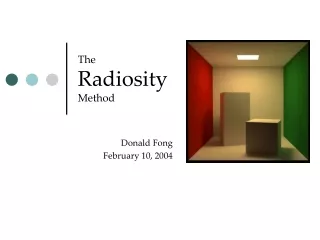
Radiosity • Surfaces in a scene reflect & emit light. • Some of this light reaches the viewer; this makes the surface visible. • But much of this reflected/emitted light will illuminate other surfaces. • This light will then reflect of these other surfaces; in fact, every surface in a scene will illuminate other surfaces in the scene.
Background needed… • Light • Light Transport • Radiometry • Reflection Functions
Light • The visible light can be polarized • Optics is the area that studies about these radiations
Optics Optics Geometric Physical Quantum Shadows Optical Interference Photons laws To study radiosity Geometric Optics is needed
Light Transportation • Light travels in the form of particles(photons) • Total number of particles in a small differential volume dV is P(x) = p(x) dV particle density P(x) = p(x) (v dt cos()) dA
Light Transportation contd.. Not all particles flow with the same speed and same direction. The particle density is now a function of two independent variables x, . Then we have P(x, ) = p(x, ) cos d dA Here d is called the differential solid angle.
Angles 2D angle 3D/Solid Angle
Solid Angle Definition :The SA subtended by an object from a point P is the area of projection of the object onto the unit sphere centered at P. Area (dA) = (r d) (r sin d)= r2 sin d d The differential solid angle : d = dA cos / r2 = cos sin d d
Radiant Energy Q Rendering systems consider the stuff that flows as radiant energy or radiant power() The radiant energy per unit volume is the photon volume density times the energy of a single photon(hc/). L(x,) = p(x, , ) (hc/) d L is called radiance
Radiometry Science of Measuring light Analogous science called Photometry is based on human perception
Radiometry contd.. The radiometric quantities that characterize the distribution of light in the environment are: • Radiant Energy • Radiance • Radiant Power • Irradiance • Radiosity • Radiant Intensity
Radiance • Radiance (L) is the flux that leaves a surface, per unit projected area of the surface, per unit solid angle of direction. n L dA
n d L dA Radiance • For computer graphics the basic particle is not the photon and the energy it carries but the ray and its associated radiance. Radiance is constant along a ray.
Properties of Radiance 1)Fundamental quantity -all other quantities derived from it 2) Invariant along a ray - quantity used by ray tracers 3) Sensor response is proportional to radiance -eye/camera response depends on radiance
Radiant Power() Flow of energy. Power is the energy per unit time. Also called as radiant flux. = dQ/dt. The differential flux is the radiance in small beam with cross sectional area dA and solid angle d d = L(x, ) cos d dA
Invariance of Radiance dF = L1 dw1 dA1 = L2 dw2dA2 dw1 =dA2 /r2 and dw2 =dA1 /r2 Throughput T = dw1 dA1 = dw2 dA2 = dA1 dA2/ r2
Irradiance Irradiance: Radiant power per unit area incident on a surface E = Li(x,w) cos q dw
Radiosity Official term : Radiant Exitance Radiosity: Radiant power per unit area exiting a surface B = Lo(x,w) cos q dw
Radiant Intensity Radiant Intensity: Radiant power per solid angle of a point source I(w) = d(F )/d(w) F = I(w) d(w) • For an isotropic point source: I(w) = F/4p
Irradiance due to a Point Light Irradiance on a differential surface due to an isotropic point light source is E = dF/ dA =I(w) d(w) dA =F cos(q) 4p |x – xs|2
Reflection Functions Reflection is defined as the the process by which the light incident on a surface leaves the surface from the same side. The nomenclature and the general properties of reflection functions are discussed.
f(p, i ,r ) i r Reflected ray Incident ray Illumination hemisphere BRDF Bidirectional Reflection Distribution Function f(x, i , r) =Lr(x,r)/ dEi(x,r) In short this is the ratio of radiance in a reflected direction to the differential irradiance that created
Properties of the BRDF • 1)Reciprocity f(x, i , r) = f(x, r , i) • 2)Anisotropy If the incident and the reflected light are fixed and the underlying surface is rotated about the surface normal, the percentage of light reflected may change.
Reflectance Equation The BRDF allows us to calculate outgoing light, given incoming light: Lr(x,r)= f(x, i , r) * dEi(x,r) =f(x, i , r) * Li(xi,w) cos q dwi Integrating over the hemisphere gives the reflectance equation: Lr(x,r)= f(x, i , r) * Li(xi,w) cos q dwi
Reflectance • Reflectance: ratio of reflected flux to incident flux r = dr/ do= Lr(r) cos q rdwr r Li(i) cos q idwi i • Reflectance is always between 0 and 1 but depends on incident radiance distribution
Lambertian Diffuse Reflection • Reflection is equal in all directions f r ,diffuse (x, i , r) is constant. Lr(x,r)= f r ,diffuse(x, i , r) * Li(xi,w) cos q dwi =f r ,diffuse(x, i , r) Li(xi,w) *cos q dwi =f r ,diffuse(x, i , r) E
Lambertian Diffuse Reflection Reflected radiance is independent of direction Therefore the radiosity is simply: B = Lr,diffuse(x,w) cos q dw • =p Lr,diffuse • = p f r ,diffuse(x, i , r) E
Lambertian Diffuse Reflection r = dr/ do= Lr(r) cos q rdwr r Li(i) cos q idwi i = Lr,diffuse cos qr dwr rE = p f r ,diffuse
Global Illumination Radiance is invariant along a ray Li(x`, i) = Lr(x, r) V(x,x`) V(x,x`) is the visibility from point x to x’ Converting the directional integral into a surface integral dwi =cos qo dA |x-x`| 2 The Projected solid angle is cos qi dwi =cosqi cosqo dA |x-x`| 2
Global Illumination Geometry term:G(x,x1) =cosqi cosqo |x-x`| 2 cosqi dwi = G(x,x1) dA • Rewriting the reflectance equation: Lr(x`,`)=f(x, -, `)L(xi,w) G(x,x’)V(x,x`)dA s
Global Illumination Reparameterizing gives: Lr(x`,`)=f(x, -, `)L(xi,w) G(x,x’)V(x,x`)dA s Lr(x`,x``)=f(x x` x``)L(x x`) G(x,x’)V(x,x`)dA Lr(x`,x``)=Lr(x`,x``)+r(x )/p *L (x x`) G(x,x’)V(x,x`)dAs s The radiance sent from x’ to x’’ is simply the amount of radiance sent from all other visible points x in the scene and then reflected to x’’
Rendering Equation • Adding in the radiance directly emitted from x’ to x’’ yields the rendering equation: Lr(x`,x``)=Lr(x`,x``)+f(x x` x``)L(x x`) G(x,x’)V(x,x`)dAs The radiance sent from x’ to x’’ is simply the amount of radiance directly emitted from x’ to x’’ plus the radiance sent from all other visible points x in the scene and then reflected to x’’
Radiosity Equation More importantly the outgoing radiance is same in all directions and in fact equals B/ p. • B(x) = E(x) +r(x ) B(x`) G(x,x’)V(x,x`)dA s p
Advantages 1)Highly realistic quality of the resulting images by calculating the diffuse interreflection of light energy in an environment. 2)Accurate simulation of energy transfer. 3)The viewpoint independence of the basic radiosity algorithm provides the opportunity for interactive "walkthroughs" of environments. 4)Soft shadows and diffuse interreflection.
Disadvantages 1)Large computational and storage costs for form factors. 2)Must preprocess polygonal environments. 3)Non-diffuse components of light not represented. 4)Will be very expensive if object(s) is moving in the scene.
References Radiosity Papers are available here 1)http://www.scs.leeds.ac.uk/cuddles/rover/radpap.htm 2)SIGGRAPH 1993 Education Slide Set, by Stephen Spencer http://www.education.siggraph.org/materials/HyperGraph/radioity/overview_1.htm Books: 1)Radiosity and Global Illumination Sillion and Puech ISBN 1-55860-277-1 2)Radiosity and Realistic Image Synthesis. Cohen and Wallace .ISBN 0-12-178270-0 Software: 1)www.acurender.com