Download
1 / 25
250 likes | 383 Views
SuperB design and needs. M. Biagini, INFN-LNF TIARA Kickoff meeting CERN, 23-24 Feb. 2011. SuperB design. SuperB is a 2 rings, asymmetric energies (e - @ 4.18, e + @ 6.7 GeV) collider with: large Piwinski angle and “crab waist” resonance compensation ultra low emittance lattice

E N D
SuperB design and needs M. Biagini, INFN-LNF TIARA Kickoff meeting CERN, 23-24 Feb. 2011
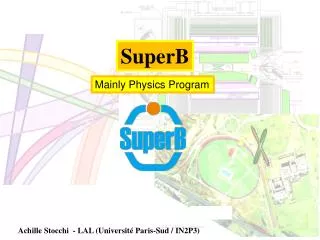
SuperB design • SuperB is a 2 rings, asymmetric energies (e- @ 4.18, e+ @ 6.7 GeV) collider with: • large Piwinski angle and “crab waist” resonance compensation • ultra low emittance lattice • longitudinally polarized electron beam • target luminosity of 1036 cm-2 s-1 • possibility to run at t/charm threshold with L = 1035 cm-2 s-1 • There will be also some SR beamlines in parasitic or dedicated running • The design requires state-of-the-art technology for emittance and coupling minimization, vibrations and misalignment control, e-cloud suppression, etc... • The design has many similarities with the Damping Rings of ILC and CLIC, and with latest generation SL sources common problems • For details see the new Conceptual Design Report (Dec. 2010) on: http://arxiv.org/abs/1009.6178
Site choice • Site choice is the present main issue • Frascati Lab is a possibility, however space available is small, and there may be conflicts with other future infrastructures • Tor Vergata University may be the optimal choice (seems available now) due to “green field” status ad vicinity to the LNF • Other sites (North and South Italy) have been proposed and will be evaluated
(May 2010 – release v12) Courtesy of S. Tomassini Circumference= 1.25 Km SuperB footprint at LNF
SuperB parameters • IP and ring parameters (see Table) have been optimized in order to: • Maintain wall plug power, beam currents, bunch lengths, and RF requirements comparable to past B-Factories • Reuse as much as possible of the PEP-II hardware • Have ring parameters as close as possible to those already achieved in the B-Factories, or under study for the ILC Damping Ring or achieved at the ATF ILC-DR test facility • Simplify IR design as much as possible. In particular, reduce the synchrotron radiation in the IR, reduce the HOM power and increase the beam stay-clear • Eliminate the effects of the parasitic beam crossing; • Relax as much as possible the requirements on the beam demagnification at the IP • Design the FF system to follow as closely as possible already tested systems, and integrating the system as much as possible into the ring design
Beam-beam tune scan Courtesy of D.Shatilov CDR, xy = 0.17 CDR2, xy = 0.097 L (red) = 1. ∙1036
SuperB flexibility • Rings are designed to have flexibility for the parameters choice with respect to the baseline. In particular: • horizontal emittance can be decreased by about a factor 2 in both rings by changing the partition number (by changing the RF frequency [LEP] or the orbit in the ARCS) and the natural ARC emittance by readjusting the lattice functions • Final Focus system as a built-in capability of about a factor 2 in decreasing the IP beta functions • RF system will be able to support higher beam currents (up to a factor 1.6) than the baseline ones, when all the available PEP RF units are installed • “Low Emittance” set relaxes the RF requirements and all the problems related to high current operations (including wall-plug power) but put more strain on optics and tuning capabilities • “High Current” set has the opposite characteristics: requirements on vertical emittance and IP beta functions are relaxed but the high currents issues are enhanced (instabilities, HOM and synchrotron radiation, wall-plug power etc…). • In all sets several parameters are kept has much constant as possible (bunch length, IP stay clear etc…), in order to reduce their impact on Detector backgrounds, HOM heating, etc…
t/charm running • In order to operate at t/charm threshold (about 3.8 GeV) with minimal modifications to the machine, the beam energies will be scaled, maintaining the nominal energy asymmetry ratio used for operation at the center- of-mass energy of the U(4S) • All magnet currents will be rescaled accordingly • In order to provide the necessary damping at low current wigglers will be installed in the straight sections (dispersion free) and in the ARCs, in a relative number matched to achieve the desired beam parameters (emittance etc…). About 15-20m of wigglers will be needed, their total lengths depends from the field in the wigglers (to be studied). The permanent magnets in the IR will be replaced with weaker versions • Main differences in the ring properties will be: • lower energy by a factor of about 2.6-2.8 per ring • longer damping time by a factor of about 2.0 per ring • decreased Touschek lifetime by a factor of 3-6 • increased sensitivity to collective effects
t/charm running • Luminosity should scale linearly with energy, however damping times and collective effects will result in a further decrease the luminosity. In general, the luminosity dependence is less then linear with respect to the damping times (about t-0.3 in beam-beam limit regime). • Given all factors, we expect that operations at lower energy will require a decrease of the beam current and an increase of the beam emittance • It is thus reasonable to expect a luminosity about 10 times smaller than that at 10.58 GeV
Latest lattice studies • Modified V12 (CDR2) 3p ARC cell lattice with alternating long and short arc cells V13 • Modified Final Focus design for better performances • Near-IP lattice with detector solenoids and compensation of coupling Some studies also performed for a shorter Ring (V14) • Lattice design is still in evolution, at present we are studying the possibility to have different length rings (LER half of HER) needs bb simulations for possible dangerous resonances (see Keil-Hirata)
Layout of HER arcs (Sep.’10) V12 V13 V14 V12 = CDR2 lattice V13 = modified V12 (new arcs) V14 = shorter ring (on hold) Courtesy of S. Sinyatkin
SuperB lattices parameter list V12 = CDR2 lattice V13 = modified V12 (new arcs) V14 = shorter ring (on hold)
Intra Beam Scattering Effect of IBS on transverse emittances about 30% in LER and less than 5% in HER, still reasonable if applied to lattice natural emittances values Interesting aspects of the IBS such as its impact on damping process and on generation of non Gaussian tails may be investigated with a multi-particle code being developed: Benchmarking with conventional IBS theories gave good results Preliminary FORTRAN (faster!) version of the code produced: Remaining features are going to be included very soon Started collaboration with M. Pivi (SLAC) to include the IBS in CMAD (parallel, faster) Started studies on full lattice (including coupling and errors) Courtesy of T. Demma
IBS evaluation methods comparison ex,z vs bunch current Courtesy of T. Demma • 3 methods used, all in good agreement: • Bane (theoretical), allows for emittance growth rates estimate • Chao (theoretical), allows for emittance time evolution estimate • 6D MonteCarlo more accurate, all of above, will include non-gaussian tails, soon to be translated from Mathematica to Fortran for speed and precision reasons (collaboration with M. Pivi, SLAC)
IBS in SuperB HER (h= v=2 s=40ms) Courtesy of T. Demma V13vsV12 R=6% R=4.8% V-emittance H-emittance R=6% R=4.3% Momentum spread Bunch length R=2.5% R=2.5% R=2.1% R=2.1%
Multi-particle tracking of IBS in LER Courtesy of T. Demma NTurn=10000 (≈10 damping times) MacroParticleNumber=10000 sz=5.0*10-3 m dp=6.3*10-4 tx = 100-1 * 0.040 sec ty = 100-1 * 0.040 sec ts = 100-1 * 0.020 sec ex=1.8*10-9 m ey=0.25/100*ex Mathematica vs Fortran implementation of the IBS multi-particle tracking code. The Fortran version is more then 1 order of magnitude faster!
Emittance growth due to head-tail instability =10x1011 =9x1011 =8x10¹¹ Input parameters for CMAD Taking into account the effect of solenoids in drifts,the interaction between the beam and the cloud is evaluated only in the magnetic regions of the SuperB HER (V12) for different values of the electron cloud density. The threshold density is determined by the density at which the growth starts: Courtesy of T. Demma
Low Emittance Tuning for LER LER ARC's tolerances evaluated using a Response Matrix technique that optimizes orbit, in order to recover the design values for Dispersion, Coupling and Beta-beating, and obtain the lowest possible vertical emittance Different sets of correctors tested, may be reduced to 109. Final Focus introduces stringent restrictions on alignment of both FF and ARCS (even for no errors in FF) Courtesy of S. Liuzzo
IR Summary Courtesy of M. Sullivan • Crossing angle back to 60 mrads • This removes some of the space for the PM slices as well as the dual quad super-conducting magnets • Presently the dimensions of these elements are “snug” but acceptable at this stage (actual engineering requirements will no doubt alter the design again) • We have two designs that work for SR backgrounds • Vanadium Permendur (with Holmium as an option) • Parallel air-core dual quads + vanadium permendur Panofsky quads on the HER • Good progress is being made on the design of the QD0 • The engineering details for the “Italian” SC design are being studied • A prototype Panofsky style QD0 is planned for the BINP C-tau design • An overall vibration control design is being developed for the FF magnets • We have a first look at correcting the effects of the detector solenoid in hand • The polarimeter design is being studied to enable measuring transverse polarization
Air core “Italian” QD0, QF1 Courtesy of M. Sullivan
Coupling correction with detector solenoid OFF Assumptions: 1) detector solenoid, bucking solenoids and anti-solenoid are OFF; 2) SC skew quad coil is ON; 3) Permanent quad QD0P rotation angle is adjustable. Correction is done using QS1,QS2, QS3,QS4 skew quads. QD0P rotation SC skew coil QS1 QS2 QS3 QS4 Skew quad locations IP CCY CCX ROT [bxby]1/2 Coupling angle after correction QD0P angle unchanged QD0P angle optimized Courtesy of Y. Novokhatski
Coupling correction with detector solenoid ON • The model assumes that the compensating solenoids in the cryostats zero out the detector field everywhere except +/- 0.55 m from the IP • First “linear” correction: as things become more stable a more sophisticated model and correction scheme can be developed that includes the non-linear terms • The designed correction system compensates each half-IR independently and contains on each side of IP: • Rotated permanent quads • Skew winding on SC quads to simulate rotation • SC anti-solenoid of strength 1.5T x 0.55 m aligned with the beam axis • 2 vertical and 2 horizontal dipole correctors for orbit correction • 4 skew quads at non-dispersive locations for coupling correction • 2 skew quads at dispersive locations for correction of vertical dispersion and slope • nominal FF quads are used to rematch the Twiss functions and horizontal dispersion Courtesy of Y. Novokhatski Anti- solen H2 V1 H1 QS1 Solen V2 Other correctors are outside of this region
Vibrations studies Courtesy of K. Bertsche • Measured ground motion at LNF (possible site?) • Must keep quad motion below 1 μm • Cantilevered cryostat should be designed for low vibration • Damp resonances and push > 10 Hz • Support cryostat on both sides of detector door • Must keep cryostat rotation below 2 μrad • Avoid building torques into magnet supports • Beam feedback should extend to > 100Hz, provide > 10x vibration reduction at LF • But we may not even need beam feedback during quiet parts of day • Vibration should not be a problem for SuperB at LNF, even at rush hour, need to be evaluated for other sites
What we would like to achieve with SVET • To learn on emittance measumement diagnostics • To apply and check Simone’s LET tools to SLS to achieve minimum emittance and coupling and detect misalignments • To collaborate in studies and simulation of IBS (most for the t/charm running) • To study coupling control methods to optimize SuperB design • To participate to MD shifts • All this with very few resources... (11.5 p-m, 9 keuro for 3 years) !