Download
1 / 42
460 likes | 923 Views
Semiconductor Nanowires. JASS 05 Yvonne Gawlina Technische Universität München. Overview. Introduction Synthesis of Nanowires - Pseudowires - Free standing nanowires Properties of Nanowires Applications. Introduction. The “first nanotechnologists” worked in the middle ages:

E N D
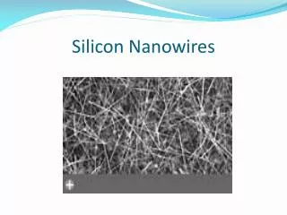
Semiconductor Nanowires JASS 05 Yvonne Gawlina Technische Universität München
Overview Introduction Synthesis of Nanowires - Pseudowires - Free standing nanowires Properties of Nanowires Applications
Introduction The “first nanotechnologists” worked in the middle ages: ® stained glass: nanoparticles of gold and silver in glass Creation of Nanowire a new challenge in modern age!
“Pseudowires” Pseudowires: wires which are enclosed in other material Methods of manufacturing: - lithography and etching ® top down - electrostatically induced wires - strain induced wires - growth on patterned surfaces - cleaved edge overgrowth
“Pseudowires” Litography and etching Create pattern Formation of 2d quantum well Coating with resist Etch, until wire remains Sometimes overgrown again to shield wire! Disadvantages: optical and electrical dead layer because of defects due to etching
“Pseudowires” Electrostatically induced wires - Creation of a Schottky contact (metal on semiconductor): - application of voltage raises/lowers the bands ® creation of “wires” for holes/electrons at certain voltages split gates: two slightly separated metal strips ® with voltage: potential minimum creates of wire of variable width disadvantage: potential minima not very deep ® only for low temperature
“Pseudowires” Strain induced wires 2d quantum wire Carbon as stressor Wires through strain Disadvantage: very small potential ® only for low temperatures
“Pseudowires” V-groove nanowires V-shape due to different etching directions Growth of barrier material Growth of wire material Growth of 2nd barrier material to sharpen groove again wire
“Pseudowires” Cleaved edge overgrowth wire Growth of quantum well rotation Growth of second quantum well Disadvantage: low temperatures needed
Synthesis of Nanowires Methods of Nanowire synthesis VLS (Vapour Liquid Solid) method Modification of VLS CVD (Chemical Vapour Deposition) LCG (Laser Ablation catalytic Growth) Low temperature VLS method FLS (Fluid Liquid Solid) mechanism SLS (Solution Liquid Solid) mechanism OAG (Oxide Assisted Growth)
Vapour Liquid Solid method Basics about phase diagrams Alloys have phase diagrams Lever rule: T liquid liquidus al + as = 1 liquid and solid solidus mixed crystal gl gtot gs B A
Vapour Liquid Solid method liquidus T liquid Eutectic A + liquid B+ liquid Mixed crystal A B solidus Eutectic: - coexistence of 3 phases - lowest temperature where system is still totally liquid - minimum of liquidus curve - solid in solid + liquid phase consists of only one material
Vapour Liquid Solid method T l B+ l A + l Mixed crystal B A - mix of semiconductor and metal - eutectic - melting point of Semiconductor with metal lower - growth of one pure material ® metal as catalyst Growth procedure: reactant vapour reactant vapour reactant vapour reactant vapour metal metal +Sc metal +Sc metal +Sc Sc Liquid catalytic nanocluster Nanowire nucleation Nanowire growth supersaturating
Vapour Liquid Solid method T liquid GaAs+ liquid Au + liquid Au + GaAs Au GaAs Synthesis of multicomponent semiconductor, like binary III-V materials (GaAs, GaP,InAs, InP) ternary III-V materials (GaAs/P, InAs/P) binary II-VI materials ( ZnS, ZnSe, CdS, CdSe) binary Si Ge alloys Pseudobinary phase diagram E.g. Au - GaAs pseudobinary phase diagram
Vapour Liquid Solid method - critical diameter, so that the liquid catalyst clusters are stable in equilibrium a = surface free energy W = molar Volume R = gas constant T = absolute temperature C = concentration of semiconductor component in liquid alloy C¥ = equilibrium concentration Problem: in fluid at according temperature ® critical diameter about d = 0.2 mm Goal: finding methods to get smaller metal clusters to start NW growth
Chemical Vapour Deposition E.g. growth of GaN nanowires in CVD reactor - Ni catalyst on Si substrate with 0.5 M Ni(NO3)2·6H2O ® drying in oven - formation of Ni islands on Si substrate - Ga and GaN powder in inner reactor - Hydrogen in outer tube to minimise side reactions until 700 °C - Ammonia gas into inner reactor ® start of nanowire growth - Nitrogen gas during cooling phase
Chemical Vapour Deposition CVD reactor 1. Vertical tubular furnance 2. Gas inlet line 3. Ni-coated Si substrate 4. Gas outlet line 5. Outer reactor tube 6. Inner reactor tube
Laser Ablation Catalytic Growth nanometer sized cluster with laser ablation SC SC SC M hn M, SC SC M SC SC SC Laser ablation Vapour condenses in cluster Supersaturation until start of wire growth Transport from growth zone
Laser Ablation Catalytic Growth LCG reactor Cold finger Focus Tube furnace Laser Target in quartz tube Gas: in Gas: out
Laser Ablation Catalytic Growth Results with LCG: with Si: - uniform Diameter down to 3 nm. - Amorphous coating, consisting of SiO2 - Nanocluster at the end of the wire, consisting of metal and Si (e.g. FeSi2) - [111] growth direction Nanowire diameter depends on nanocluster catalyst diameter: Nanocluster nm 4.9 +/- 1.0 9.7 +/- 1.5 19.8 +/-2.0 30.3 +/- 3.0 Nanowire nm 6.4 +/- 1.2 12.3 +/- 2.5 20.0 +/- 2.3 31.1 +/- 2.7
Low temperature VLS method - metal with low melting point (e.g. Ga ,In, Bi..) - eutectic with very low semiconductor content - silane decomposition by atomic hydrogen e.g. SiHx(g) + xH(g) ® Ga-Si(l) + xH2(g) Ga
Low temperature VLS method a = surface free energy W = molar Volume R = gas constant T = absolute temperature C = concentration of semiconductor component in liquid alloy C¥ = equilibrium concentration E.g. T = 400°C and 1% of Si ® d = 6nm usually with Si conc. of about 20-30 % ® d= 0.2 mm E.g. Ge with Ga forms eutectic at only 30 °C!
Fluid Liquid Solid mechanism E.g growth of Si nanowires - alkanethiol coated Au nanocrystals (d = 6.7 +/- 2.6 nm) tethered on Si substrate - diphenysilane (C12H12Si) decomposes in supercritical cyclohexane (C6H12) Si Si Si Si Si Si Si Au Au Au SiO2 SiO2 SiO2 Si Si Si
Fluid Liquid Solid mechanism FLS reactor manipulation of NW: - metal seed density and size - Diphenylsilane rate - Temperature - T small: few nanoparticles but nanowires curled - T high: straight nanowires but more nanoparticles
Solid Liquid Solid mechanism E.g. amorphous Si nanowires with SLS Si nanowires Si - Ni alloy Ni Si substrate Si Si Si Si Si Si Si Si Heat Heat Heat Ni coated Si substrate Heat ® diffusion of Si into Ni Supersaturating of Ni Growth of Si nanowires
Oxide Assisted Growth - Oxides as catalyst instead of metal - production of Ge nanowires, Si nanowires, carbon nanowires, silicon and SnO2 nanoribbons, Group III - V and II - VI compound semiconductor nanowires Ge nanowires Silicon nanoribbons
Oxide Assisted Growth Process of OAG for Si: - SiO2 powder added to Si (SiO2 needed throughout process) - ablation of powder - silicon sub-oxides form bonds with Si substrate - “dangling bonds” act as nuclei - Si takes places of oxide ® start of nanowire growth and outer layer of SiOx
Oxide Assisted Growth [110] [001] - kinds of silicon oxide cluster: + oxygen rich cluster + silicon rich cluster + silicon monoxide like clusters (Si : O = 1:1) - highest reactivity in Si rich cluster - growth surpressed in certain directions yield Triangle [110] Rough circle [110] Rough rectangle [112] Pentagon [001]
OAG, VLS and temperature For Si: T = 1100 °C - 1200 °C : d gets smaller with decreasing T, metal found in wire ® VLS mechanism with [111] as favoured growth direction T = 850 °C - 1050 °C : no metal in wire ®OAG region, diameter not dependant on T T = 1100 °C : Coexistence of OAG and VLS
Nanowires Summary of some single crystal nanowires synthesised Minimum d in[nm] Ratio of components structure Material GaAs GaP GaAs0.6P.0.4 InP InAS InAs0.5P0.5 Zns ZnSe CdS CdSe Si1-xGex 3 3-5 4 3-5 3-5 3-5 4-6 3-5 3-5 3-5 3-5 Zinkblende Zinkblende Zinkblende Zinkblende Zinkblende Zinkblende Zinkblende Zinkblende Wurtzite Wurtzite Diamant 1.00 : 0.97 1.00 : 0.98 1.00 : 0.58 : 0.41 1.00 : 0.98 1.00 : 1.19 1.00 :0.51 : 0.51 1.00 : 1.08 1.00 : 1.01 1.00 : 1.04 1.00 : 0.99 Si1-xGex
Properties of Nanowires PL characterisation PL dependence on direction: parallel ® “on” perpendicular ® “off” - intensity uniform along wire - periodic cos2a dependence
Properties of Nanowires Size Dependant PL - Shift to higher energies with decreasing diameter - Quantum confinement effects below d = 20nm - T - dependant shift
Properties of Nanowires Size Dependant PL Theory: particle in an infinite cylinder Wave function: Energy shift
Properties of NW Polarised excitation and emission Polarisation rate: Most nanowires r = 0.96 Theory: infinite dielectric cylinder in vacuum and laser is constant Excitation emission Solid line: parallel dashed line: perpendicular ® with e = 12.4 for InP ®r = 0.96
Properties of NW Polarised Photodetection photodetector Conductance vs. power density: upper branch: light parallel polarised lower branch: light perpendicular polarised Conductance vs. polarisation angle
Properties of NW Thermal conductivity Cv= specific heat v = velocity of phonons l = mean free path Mean free path for phonons in solids in the nm range Alteration of phonon transport in nanowires: - more boundary scattering - changes in phonon dispersion relation - quantization of phonon transport
Properties of Nanowires Thermal conductivity Si NW thermal conductivity 2 orders of magnitude smaller than in bulk Si Deviation from the Debye T3 law
Properties of NW Doping - possible to dope nanowires, e.g silicon: boron doped ® p-type phosphor doped ® n-type Lightly doped Heavily doped ® metallic ® many new exciting possibilities for application of nanowires
Applications - Nanowire heterostructures + axial heterostructures, e.g GaP-GaAs heterojunction + radial heterostructures, e.g. Si-Ge + Nanowire superlattices
Applications - Sensors + pH sensors + gas sensors (e.g. Ammonium, Water) - Single mode optical wave guides Gas in Gas out
Applications - Nanophotonics + nanoLEDs (p and n type nanowires in crossed nanowire device ® light from crossing point at forward bias) - Nanoprobes + Tips for Atomic Force Microscopy - High temperature, high current superconductors - Lasers (electrically driven) - nanoFETs etc.
Summary Synthesis Pseudowires Free standing Nanowires Properties PL Thermal Doping Applications