Download
1 / 9
100 likes | 227 Views
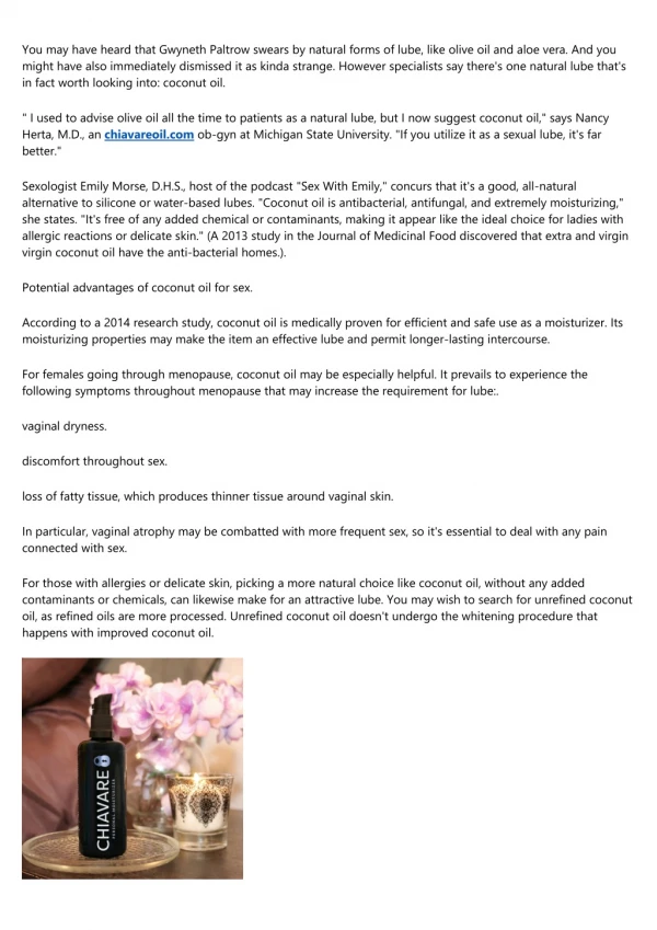
Vibration and Lube Oil Pressure Switch installation and monitoring. Higgins Station. Table of Contents. History Desired Goal Equipment Installed To Meet Goals Final Outcome. History. Lube oil pressure switch set to 8 psig decreasing.

E N D
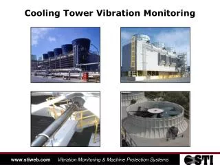
Vibration and Lube Oil Pressure Switch installation and monitoring Higgins Station
Table of Contents History Desired Goal Equipment Installed To Meet Goals Final Outcome
History Lube oil pressure switch set to 8 psig decreasing. Pressure switches would fill with rain through flex conduit. Pressure switches would drift or fail closed giving indication of adequate pressure. Setting and maintaining oil pressures were labor intensive and unreliable. Pressure on gauge wouldn’t mach pressure switch.
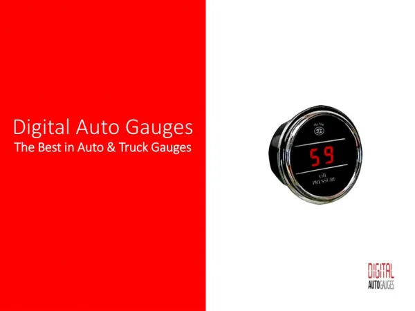
Desired Goal Pressure trip set points that would not drift. Local indication of pressure that would match what the pressure switch was seeing. Monitor pressures and vibrations from one location to aid in trouble shooting.
Equipment Installed To Meet Goals We decided on UE pressure transmitters with solid state switches integrated in them. We mounted them on the side of the cable tray at each gear box and ran a steel braided hose through the grating to the gear box. We mounted a termination box for vibration probes to monitor gear box and motor.
Equipment Installed To Meet Goals The two vibration probes are mounted directly to the motor and gear box.
Equipment Installed To Meet Goals Both the vibration and the pressure signals go to the ground floor to an OPTO 22 PLC that sends the values back to a OPTO server in our engineering room. Enter pressure and vibration readings into our PI system for evaluation.
Equipment Installed To Meet Goals We set up a PI graphic that is very helpful in seeing the overall health of our ACC fans and spotting any problems that might be taking place. Fan Running Hi or Low. Oil Pressure. Vibration on Gearbox and motor. Weekly trending.
Final Outcome Maintain our oil pressures at a consistent level with substantial cut to maintenance man hours. See when oil filters need cleaned at a glance. Assess the degradation of the gear box oil pumps which helps us in scheduling maintenance. Local pressure readings and trip pressures match. Pressure trip switches that are reliable and don’t drift. See motor and gear box vibrations as they become an issue using PI. (Looking to add into Smart Signal in the future.) Isolate pressure transmitter and switch for maintenance without removing grating.