Download

1 / 42
440 likes | 668 Views
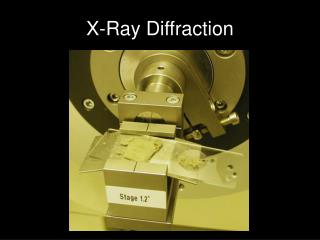
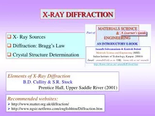
X-RAY DIFFRACTION TECHNIQUE. Dr. Pramod Kumar Singh School of Basic Sciences & Research School of Engineering and Technology Sharda University, Greater Noida, INDIA E mail: pramodkumar.singh@sharda.ac.in http://pramodkumarsingh.weebly.com. X-ray Diffraction

E N D
X-RAY DIFFRACTION TECHNIQUE Dr. Pramod Kumar Singh School of Basic Sciences & Research School of Engineering and Technology Sharda University,Greater Noida, INDIA E mail: pramodkumar.singh@sharda.ac.in http://pramodkumarsingh.weebly.com
X-ray Diffraction There are number of physical methods for investigating the structures of solids. Each technique has its own merit and weaknesses. The most important X-ray diffraction *Fingerprint characterization of crystalline materials *Determination of their crystal structures.
*Invisible *Penetrate inside of materials
X-ray Diffraction Optical grating and diffraction of light Diffraction of light by an optical grating. An optical grating may consist of a piece of glass on which have been ruled a large number of accurately parallel and closely spaced lines. The separation of lines should be a little larger than the wavelength of light, say 10,000 Å.
Consider what happens to a beam of light which hits the grating perpendicular to the plane. A piece of glass without the lines would simply transmit the light
*In the grating lines act as a secondary point sources of light and radiate light in all the directions. Interference then occurs between the waves originating from each lines source.
In certain directions, adjacent beams are in phase with each other and constructive interference occurs to give a resultant diffracted beam in the direction. When the beams are out of phase, they cancel each other and the net intensity becomes zero
Production of X-rays • X-rays are produced when high speed electrons are suddenly stopped by a solid object. • Of the total energy supplied, only a fraction (about 1%) is converted to X-rays. • Most of the energy is transferred into heat. • To prevent the target from melting, it is cooled from behind by running water. • Thus the target material must be made of a high melting material which has good thermal conductivity. • For the production of high intensity X-rays a target element should have a high atomic number. • Pure transition metals such as Mo, Cu, Cr etc. are typical target materials.
Imagine an atom consisting of a nucleus surrounded by a system of electrons contained in shells called K, L, M etc. as shown in Figure. The electrons in K, L and M shells are the electrons with principal quantum number 1, 2 and 3 respectively.
An electron bombarding the target may have sufficient energy to completely displace a K electron from the target atom. This produces an unstable ion, and 10-4 sec. later an electron from an outer shell drops into the vacant position.
This transition is accompanied by the emission of a characteristics X-ray If the vacancy is filled by an M electron then the photon produced is called a Kb1 X-ray. If the vacancy is filled by an L electron the a Ka1 or a Ka2 X-ray is produced, depending on the sub shell of the electron.
Diffraction of X-rays from crystals By 1912 the nature of X-rays – whether they were particles or waves was unresolved. This was eventually achieved by von Laue using a crystal of copper sulphate as the diffraction grating. X-ray diffraction by a crystal of beryl using the Laue method.
Diffraction of X-rays from crystals Crystalline solids consist of regular arrays of atoms, ions or molecules with inter atomic spacing of the order of 100 pm. For diffraction to take place, the wavelength of the incident light has to be of the same order of magnitude as the spacing of the grating. Because of the periodic nature of the internal structure, it is possible for crystals to act as a three dimensional diffraction grating to light of a suitable wavelength: a Laue photograph is shown in the figure X-ray diffraction by a crystal of beryl using the Laue method.
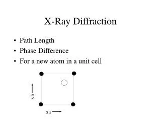
Figure illustrates the Bragg condition for the reflection of X-ray by a crystal. The array of black points (section through a crystal) Lines joining the dots mark a set of parallel planes with Miller indices hkl and interplanar spacing dhkl. Path difference EF+FG EF + FG = 2d Sin The intensity of the diffracted beam will be maximum if the path difference is an integral multiple of wavelength 2d Sin = n This is Braggs equation
Figure illustrates the Bragg condition for the reflection of X-ray by a crystal. The ray A is scattered by the atom at B and the ray D is scattered by the atom at F. For the reflected beams the Path difference EF+FG EF + FG = 2d Sin 2d Sin = n This is Braggs equation The intensity of the diffracted beam will be maximum if the path difference is an integral multiple of wavelength
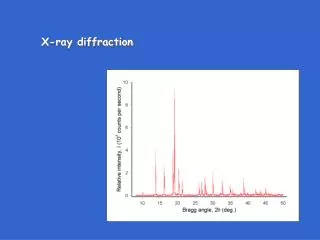
Linear (1D) Diffraction Scans have better resolution and less noise
Applications of X-ray-diffraction • The methods of X-ray diffraction has been used for more than 100 years to identify and characterize crystalline phases in solid materials • XRD technique is a powerful tool to distinguish between crystalline and amorphous materials • It is used for qualitative and quantitative analysis of crystalline materials
Applications of X-ray-diffraction • X-ray diffraction from single crystals are used for crystal structure determinations • Powder X-ray diffraction is used for lattice parameter determination of crystal lattice • Powder X-ray diffraction is used for study of solid state reactions
Qualitative analysis For qualitative analysis powder X-ray diffraction technique is used. Modern instruments have computer programme for qualitative analysis The pattern of each phase depends on its crystal structure and chemical composition The pattern is treated simply as a set of peaks , each with a position and intensity
Qualitative analysis The pattern for a mixture of phases is a simple combination of patterns of individual phases Qualitative XRD analysis compares the pattern to a library of patterns of known materials The most commonly used library is the Powder Diffraction File (PDF) or JCPDS-ICDD data Joint Committee on Powder Diffraction Standards-International Center for Diffraction Data
Databases such as the Powder Diffraction File (PDF) contain d, I lists for thousands of crystalline phases. • The PDF contains over 200,000 diffraction patterns. • Modern computer programs can help you determine what phases are present in your sample by quickly comparing your diffraction data to all of the patterns in the database. • The PDF card for an entry contains a lot of useful information, including literature references.
Quantitative analysis Some suitable internal standard is used The ratio of intensity of one phase of the material to the intensity of the internal standard is calculated and a calibration curve is plotted From the calibration curve the quantity of the particular material is determined
NaCl KCl Uses: different structures NaCl Even if two structures are the same (and they are chemically similar) differences can be observed: Peak positions (unit cell changes) and relative intensities (atoms) KCl
Uses: different structures Zeolite A Zeolite A BUT, sometimes you can’t really see any changes on visual inspection… This often happens in “open” structures where there is space for change of light atoms
Uses: polymorphs Different polymorphs will have different powder patterns e.g. Zn S
Peak Broadening In an X-ray diffraction pattern, peak width depends on • the instrument • radiation not pure monochromatic • Heisenberg uncertainty principle • focussing geometry • the sample… - a crystalline substance gives rise to sharp lines, whereas a truly amorphous material gives a broad “hump”. What happens between the two?
Peak Broadening Scherrer’s Formula • t = thickness of crystallite • K = constant dependent on crystallite shape (0.89) • = x-ray wavelength • B = FWHM (full width at half max) or integral breadth • 0B= Bragg Angle B is the line broadening, by reference to a standard (Bs), and BM is that of materials, so that
When to Use Scherrer’s Formula • Crystallite size <1000 Å • Peak broadening by other factors • Causes of broadening • Size • Strain • Instrument • If breadth consistent for each peak then assured broadening due to crystallite size • K depends on definition of t and B • Within 20%-30% accuracy at best
1050oC 30oC Uses: particle size determination Here we see particle size increasing with temperature
Particle size determination: Example Peak at 28.2° 2 with FWHM of 0.36° 2 Standard material has FWHM of 0.16° 2 = CuK = 1.540 Å 0.36 ° = 0.36 x /180 = 0.0063 rad 0.16 °= 0.16 x /180 = 0.0028 rad B = 0.0056 rad t = 255 Å = 0.0255 m
Uses: more advanced Structure refinement – the Rietveld method A refinement technique, not determination Whole-pattern fitting - not just the Bragg reflections Needs a MODEL - pattern calculated from model, compared point-by-point with observed pattern. Originally developed (1967,1969) for use with neutron data - good reproducible peak shapes 1977 - first report of application to X-ray data Hugo Rietveld, b1932 http://home.wxs.nl/~rietv025/
Uses: Rietveld Refinement Here there was a similarity between the powder pattern of this phase and an existing one – also chemical composition similar.
Uses: more advanced Naïve approach - relative intensity of peak maxima? - Consider mixture of Ba,Si,O - Ba component would scatter more than Si component (e.g. Ba2SiO4 c.f. SiO2) • Quantitative phase analysis (how much of each) Thus uses Rietveld method and takes into account relative scattering from each crystalline phase