Download
1 / 11
130 likes | 478 Views
Bit Shift Left (BSL). The BSL instruction loads data into a bit array on a false-to-true rung transition, one bit at a time. The data is shifted left through the array, then unloaded, one bit at a time. File The address of the bit array to be shifted. Control

E N D
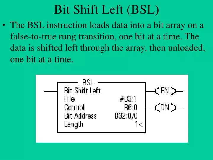
Bit Shift Left (BSL) • The BSL instruction loads data into a bit array on a false-to-true rung transition, one bit at a time. The data is shifted left through the array, then unloaded, one bit at a time.
File The address of the bit array to be shifted. Control Contains the instruction bits, the Length of the array, and the bit pointer. /EN = enable; /DN = done; /ER = error; /UL = unload. Bit Address The location of the bit which will be added to the array. The bit address must be specified to the bit level. Length The total number of bits to be shifted by the BSL. Max 16000 In PLC50
Bit Shift Right (BSR) • The BSR instruction loads data into a bit array on a false-to-true rung transition, one bit at a time. The data is shifted right through the array, then unloaded, one bit at a time.
Shift registers Shift registers can be used in control programs any time data must flow with the product in a synchronous system where the number of data bits is small. For more than four data bits, a word shift register is a better choice. Shift registers are commonly used on index tables or indexer driven lines with all carriers fastened to a chain or belt.
Shift registers One advantage of using shift registers is that they are self clearing. For example, if a line person pulls a product out of a carrier on an indexed line, the part in place bit will be wrong for the position. This may cause some problems for that position as it travels down the line, and when it reached the end of the assembly line it will fall out of the shift register and be cleared.
BTD The BTD instruction is an output instruction that moves up to 16 bits of data. The source remains unchanged. The instruction writes over the destination with the specified bits. The processor does not save the overflow bits.
Source The address of the source word in a binary or integer file. The source remains unchanged. Source Bit The number of the bit in the source word from which to start the move. Dest The address of the destination word in a binary or integer file. The instruction writes over any data already stored at the destination. Dest Bit The number of the bit in the destination word where the processor starts copying the bits from the source word. Length The number of bits to be moved.