Download
1 / 13
130 likes | 209 Views
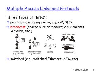
Multiple Links Failover Mechanism for RPR Interconnected Rings. zhaisuping@huawei.com yanw@huawei.com IEEE802.17 WG Orlando, Florida USA March 11~16, 2007. Multiple Link Failures Scenario.

E N D
Multiple Links Failover Mechanism for RPR Interconnected Rings zhaisuping@huawei.com yanw@huawei.com IEEE802.17 WG Orlando, Florida USA March 11~16, 2007
Multiple Link Failures Scenario When there are two failure links in the interconnected RPR rings, and these two failure links are separated by the interconnected stations. There is way to protect the traffic to be not impacted by the defect. Note: If the two failure links are not separated by the interconnected stations, or if the failure links are more than two, then traffic are always impacted, and there is no need to consider the mechanism to protect the traffic. Or else introduce the complexity with the minimal probability. Although the probability for two link failures are also minimal, if the traffic can be protected at the tiny cost, is it worthwhile to do it?
Multiple Links Failover Mechanism For the different load balancing scheme, the multiple links failover mechanism should be the same. It’s possible that this same mechanism will result in the different behaviors in the different load balancing schemes.
VLAN Balancing Failover Example Note: The blueandredline indicates the data transmission path. Through topology database, the interconnected stations are aware of the two link failures. To protect the traffic in the local ring and across the rings, two interconnected stations become both active nodes for any VLANs. After the defect is recovered, there should be some mechanism to prevent the data loop.
VLAN Balancing Failover Example - Cont After the defect disappears, for the unknown unicast/broadcast frames, to avoid the loop, the following steps are executed, 1) RB1 and RB2 send the control message to declare the defect recovery, and behave as if the defect still exists, keep in the protection state. That means, if the wrap protection mode is used, then the RB1 and RB2 are still in wrap mode, if the steering protection mode is used, RB1 and RB2 will not send any frame to the recovered link. 2) After receive the defect recovery message, RI1 and RI2 will go back to the normal state, that is one is in the active state and the other one is in the standby state for the specified VLAN. 3) Then RI1 and RI2 will send the acknowledge message to inform RB1 and RB2 to go to normal state from protection state. Or alternatively in order not delaying the topology convergence, after the defect disappears, RB1 and RB2 can temporarily set the MTU to for example 64bytes to let the RPR control frame go through, but block the data frames. After receiving the acknowledge message from RI1/RI2, MTU go back to normal value. Step 1 Step 2 Step 3 Note: The green line indicates the control message transmission path.
Spatial Balancing Failover Example Note: The blueandredline indicates the data transmission path. Through topologies database, the interconnected stations are aware of the two link failures. To protect the traffic in local ring and across the rings, two interconnected stations both should forward the traffic across the ring, and the flooding scopes are all around the ring separately. After the defect is recovered, there should be some mechanism to prevent the frame duplication.
Spatial Balancing Failover Example -Cont After the defect disappears, for the unknown unicast/broadcast frames, to avoid the loop, the following steps are executed, 1) RB1 and RB2 send the control message to declare the defect recovery, and behave as if the defect still exists, keep in the protection state. That means, if the wrap protection mode is used, then the RB1 and RB2 are still in wrap mode, if the steering protection mode is used, RB1 and RB2 will not send any frame to the recovered link. 2) After receive the defect recovery message, RI1 and RI2 will go back to the normal state, that is two nodes will coordinate to forward the traffic across the ring, using the TTL scoping the traffic to prevent the frame duplication. 3) Then RI1 and RI2 will send the acknowledge message to inform RB1 and RB2 to go to normal state from protection state. Or alternatively in order notdelaying the topology convergence, after the defect disappears, RB1 and RB2 can temporarily set the MTU to for example 64bytes to let the RPR control frame go through, but block the data frames. After receiving the acknowledge message from RI1/RI2, MTU go back to normal value. Step 1 Step 2 Step 3 Note: The green line indicates the control message transmission path. The blueline indicates the data transmission path.
Hashing Balancing Failover Example For the Hashing balancing scheme, when in the multipoint link failures, the interconnected stations behave more like the interconnected stations of the VLAN balancing scheme. Only the active/standby state is substituted for the Hash 0/1 states at the interconnected stations.
Interconnected station failure • An observation: the interconnected station failure is equivalent to the multiple link failures, the alike failover mechanism can be used. • Based on this observation, the following slide consider another interconnect RPR ring deployment, and the corresponding link failover mechanism.
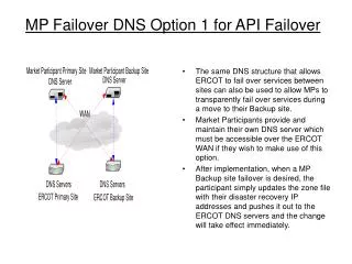
Link failover in the following deployment scenario When use the above network topology, in case of the interconnected link failure: • For the VLAN load balancing scheme, when the link connected to the station which is in the active state fails, then it transits to the standby state immediately, the interconnected stations which is in the standby state becomes the active state. • For the TTL based load balancing scheme, any one of the interconnected links fails will result in the interconnected station on the other link takes the responsibility to forward the traffic all around the ring. • For the Hash load balancing scheme, any one of the interconnected links fails will result in the interconnected station on the other link becomes both 0/1 states, and forwards all the frames with whatever hash value is.
Link failover in the following deployment scenario-Cont When the defect disappears, • For the VLAN load balancing scheme, only after the original standby station goes back to the standby state, then the original active station can forward the traffic across ring normally. • For the TTL based load balancing scheme, only after the interconnected RPR station, which resides on the defect free link, changes the state to the coordinated forwarding through TTL, then another interconnected RPR station on the recovered links can begin to forward the traffic across the ring. • For the Hash load balancing scheme, only after the original hash 0 station goes back into 0 state, then the original hash 1 state station can begin to forward the traffic across ring normally.
Link failover in the following deployment scenario-Cont • For the Hash and VLAN load balancing scheme, it’s necessary that the directly connected bridges act as the same state, i.e., both as the active (standby) or both as 0 (1) state. That means the extra synchronization message is needed between the two directly connected hybrid bridges. • Whatever the load balancing scheme is, • The link detection mechanism between the interconnected bridges is needed, or else adapt the link failure notification from the server layer to monitor the link liveness. • When the interconnected link failure is detected by one of the interconnected bridges, there should be indication to the other bridge on the local ring to change the state, in order to protect the traffic in the local ring and across the ring. • An observation: In this situation, it’s somewhat alike with the interconnected station failure in the Topology A, except that the station failure in Topology A can be detected through the TP database directly.