Download
1 / 32
320 likes | 658 Views
A Formal Methodology for Smart Assembly Design. A Presentation by Kris Downey – Graduate Student Alan Parkinson – Faculty Member 15 June 2000 Acknowledgements to NSF Grant 0084880. Presentation Outline. Introduction Research Objectives Current design techniques and analysis methods

E N D
A Formal Methodology for Smart Assembly Design A Presentation by Kris Downey – Graduate Student Alan Parkinson – Faculty Member 15 June 2000 Acknowledgements to NSF Grant 0084880
Presentation Outline • Introduction • Research Objectives • Current design techniques and analysis methods • Case study • Current status of research • Conclusions
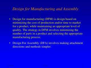
Robust Design • Design that works properly when subjected to variation • Current robust design methods • Focus on key characteristics • FMEA • DOE by Taguchi • Six sigma analysis • Optimization techniques
Smart Assembly • A smart assembly has features, not otherwise required by the function of the design, which allow the design to absorb or cancel out the effects of variation [Parkinson, 2000]
Smart Assembly • Examples of smart assembly features • Slotted holes • Springs used for positioning • Screw locators • Sliding locators • Shims
Smart Assembly • Types of smart assemblies Passive Shim Screw Inclined Plane
Smart Assembly • Types of smart assemblies Passive Can Opener Support
Smart Assembly • Types of smart assemblies Passive Car frame
Smart Assembly • Types of smart assemblies Active Scissors Gear
Smart Assembly • Types of smart assemblies Active Garage Door Roller Bearing
Research Objectives • Create a smart feature implementation methodology • Principles developed for methodology • Proven analysis methods implemented into methodology • Apply methodology to case studies
Current Design Techniques and Analysis Methods • Exact constraint design • Very close relationship to smart assembly design • Screw theory • Constraint information inferred from analysis • Tolerance analysis • Critical dimension information provided
Exact Constraint Design • Degrees of freedom 3 in 2D space 6 in 3D space
Exact Constraint Design • Constraint • A mechanical connection between objects that reduces the degrees of freedom of each object 2D constraints 3D constraints
Exact Constraint Design • Exactly one constraint for each degree of freedom • Rules for exact constraint design: 2D space 3D space • No two constraints collinear • No four constraints in a single plane • No three constraints parallel • No three constraints intersect at a point • No four constraints are parallel • No four constraints intersect at a point • No four constraints in the same plane • More mathematically-based theory is needed in this area Taken from [Blanding, 1999] and [Skakoon, 2000]
Exact Constraint Design • Exactly one constraint for each degree of freedom Underconstrained Exactly constrained Overconstrained
Exact Constraint Design • Conclusions: • Exact constraint design very closely related to smart assembly • Smart assembly provides solution to overconstrained designs
Screw Theory • Allows determination of over- or underconstrained designs • Motion analysis • Performed on individual part of assembly • Assumes parts do not break contact • Each joint type has distinct screwmatrices Taken from [Ball, 1900], [Roth 1966], [Konkar, 1993], and [Adams, 1998]
Screw Theory • Steps to constraint analysis • Translate joints into twists • Find reciprocal wrench of each twistmatrix • Union of wrenches • Find reciprocal twist of wrench • Resultant twistmatrix
Screw Theory • Interpretation of resultant twistmatrix and wrenchmatrix • Twist rows = degrees of freedom • Wrench rows = overconstraints Motions Z-Rotation Constraints Y-Translation Z-Translation X-Rotation Y-Rotation
Screw Theory • Conclusions: • Screw theory can determine if a design is over- or underconstrained • Location of idle degrees of freedom identified • Information useful to smart assembly design
Tolerance Analysis f • Vector loop analysis (DLM) • Sensitivity matrix • Results provide useful information regarding critical part dimensions • 80% of variation in angle f is attributed to dimension a • Conclusion: Sensitivity matrix determines preferred location of smart features
Case Study Taken from Kodak design problem • Baffle design • Overconstrained in z-direction Taken from [Kriegel, 1994]
Case Study • Solution #1 • Reinforce baffle and frame • Results: • Less deflection • Does not address constraint problem • Tabs tear from baffle Taken from [Kriegel, 1994]
Case Study • Results: • Variation absorbed • No deflection • Expensive parts • Increased assembly costs • Solution #2 • Double screw • Smart feature Taken from [Kriegel, 1994]
Case Study • Results: • Variation absorbed • No deflection • “No cost” solution • Minimal assembly costs • Solution #3 • Double-slotted tabs • Smart feature Taken from [Kriegel, 1994]
Case Study • Conclusions: • Worst case tolerance analysis contributed to need of smart features • Overconstrained design was not initially recognized • Smart features allowed variation absorption • Some smart features are more expensive than others
Current Status of Research • Principles of smart assembly being considered and explored • Implementation as nesting forces • Absorption of tolerances • Elimination of overconstraint • Use in designs where redundant constraints are necessary
Smart Assembly Principles • Smart assembly features as nesting forces • Eliminate mechanical play and assembly stresses Rigid constraint Smart feature
Smart Assembly Principles • Tolerance absorption • When other methods are not sufficient Spring Part A Part A Part B Part B Total gap No gap
Smart Assembly Principles • Redundant constraints become smart features • Eliminate assembly stresses
Conclusions • Research Objectives: • Create a smart feature implementation methodology • Principles inferred from existing designs: • Smart features replace overconstraints • Smart features absorb tolerances in exactly constrained designs • Smart features implemented as nesting forces • Proven analysis methods adapted for methodology • Exact constraint design, screw theory and tolerance analysis • Apply methodology to case studies • Indirect absorption of variation