Download
1 / 28
300 likes | 518 Views
Interactive Catalog. Fully-Automated Optical Frequency Counter. MF-5802A. Root MENU. 1. Product Information. 2. New Horizon with Optical Frequency. 3. What is Optical Frequency Comb?. 4. About Optical Comb Inc. 5. Nobel Prize and Optical Comb. Optical Comb, Inc.

E N D
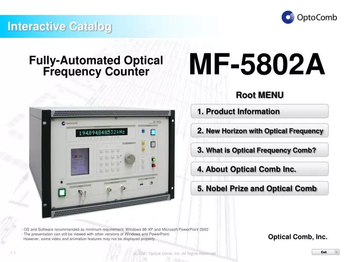
Interactive Catalog Fully-Automated Optical Frequency Counter MF-5802A Root MENU 1. Product Information 2. New Horizon with Optical Frequency 3. What is Optical Frequency Comb? 4. About Optical Comb Inc. 5. Nobel Prize and Optical Comb Optical Comb, Inc. • - OS and Software recommended as minimum requirement: Windows 98-XP and Microsoft PowerPoint 2002 • The presentation can still be viewed with other versions of Windows and PowerPoint. • However, some video and animation features may not be displayed properly. 1-1 Exit ×
High-precision measurement with a Nobel Prize-winning technology Product Overview Fully-automated optical frequency counter MF-5802A offers all necessary functions such as frequency-stabilized laser, optical comb generator, optical frequency measurement system, etc. in one unit. Connect the input light source to be measured (in C-band or 1530-1565nm) to the device and press the START button, and it displays the optical frequency in the order of 1MHz (9 digits). This product uses the technology that was awarded the Nobel Prize in Physics announced on 4th October 2005. The product has made the “laser-based precision spectroscopy using the optical frequency comb technique” available in the market in the form of an all-in-one unit. The product has great potential to bring about a breakthrough not only to the development of optical communication devices and equipment but also to optical measurement for non-communication purposes. Optical Frequency Counter MF-5802A MENU 1-2
Simple and Easy Operation – Video Demo Click anywhere on the photograph to play (30 seconds) (N.B. The video features an old model; The basicfunctionalities remain unchanged in the latest products.) MENU 1-3
Friendly Interface and Powerful Specifications ・USB port and USB flash memory slot for data transfer ・Optical frequency display: 12 digits (Significant digit: 9) Digital VFD ・5.7 inch (240 x 320dpi)color LCD display ・Extra hard disk space for storing measurement data and analytical software MENU 1-4
Greater Accuracy than Conventional Measuring Methods 193107765 201 189 kHz . . . T G M k START ANIMATION MF-5802A Display digit - 9 digits (Frequency accuracy1MHz) MENU 1-5
USB Port for Enhanced Connectivity with PC External communication interface - USB 1.1 cable is recommended as minimum requirement Link to Host Computer - Windows XP, Windows2000 The following are also possible in conjunction with a PC: - More detailed data analysis - Data storage in CSV format - Performance test of this unit USB port Optical frequency counter connected with a laptop PC (N.B. The photo features an old model) MENU 1-6
Analytical Functions Best Utilizing Built-in Software & External Interface Built-in Analytical Software The built-in Allan variance software to analyze the maximum, minimum and mean values in a “stand-alone” manner. Library Function (Optional) In addition to the above built-in software, the library (optional) offers the additional capability of controlling the optical frequency counter and data gathering. Frequency Measured by Optical Frequency Counter (194213427281kHz) Frequency Error [kHz] Time (10s gate) [s] Example analysis: Optical frequency measured and plotted in a graph MENU 1-7
End of Chapter-1 How will the advent of this highly-accurate measuring method change the world of optical engineering? Go to Chapter-2. “New Horizon with Optical Frequency” MENU 1-8
New Horizon with Optical Frequency We have developed MF-5802A to achieve the following three goals: • Realization of optical frequency standard (comparable with • the calibration services of the National Standard Body) • 2. Measuring device suitable for optical communications (DWDM etc.) • with increasingly high accuracies. • 3. Precise measurement of optical component • and devices. In order to overcome: ・The barrier of accuracy the conventional methods cannot break through. ・Limited accuracy of existing measuring devices that restrict the future potential of R&D activities. MENU 2-9
Behind the Development-Demand for Highly-Accurate Optical Frequency Measurement In addition, there was demand for “highly-accurate optical frequency measurement” driven by the trend of the industry behind the development of MF-5802A. There was no optical frequency (wavelength) standards available for the 1.5um range, which is an important wavelength in optical communication and other areas. Traditionally, indirect wavelength measurement method utilizing the 633nm wavelength of Iodine stabilized He-Ne lasers (such as off-the-shelf wavelength meter using Michelson interference method) was the only way for calibration for this wavelength range. Institute of Electronics, Information and Communication Engineers 2002 Optical Frequency Standards at Telecommunication Region – From Wavelength Measurement to Optical Frequency Measurement – Atsushi Onae; Ken’ichi Nakagawa (Guest Authors) "One of the best known optical frequency standards is Iodine (I2) stabilized He-Ne laser with visible wavelength range of 0.633um. However, despite the longtime demand, there has been no effective standards available for the 1.5um wavelength range for WDM communication." The Laser Society of Japan2002 Accurate Optical Frequency Standards in the Optical Fiber Communication Band - Ken’ichi Nakagawa Click ! MENU 2-10
Solutions Offered by MF-5802A Conventionally, Optical wavelength was measured using a wavelength meter or an optical spectrum analyzer With MF-5802A... Click ! Optical frequency can be measured directly with optical frequency counter. Disadvantages of conventional measuring methods 1. Limited accuracy 2. No future potential to meet increasing demand for higher accuracy. With MF-5802A… Click ! Dramatic improvement of accuracy. A frequency precision of 1 MHz made available with allmodels from M-5802A. MENU 2-11
Suggested Applications 1. Precise measurement for the output frequency of the light source DFB laser, stabilized laser, etc. 2. Measurement of high precision optical components TFF, FBG, AWG, etc. 3. Calibration of Wavelength Meter MF-5802A shows the “status of light,” which could not be seen with conventional wavelength meters, and contributes to the evolution of your R&D activities! MENU 2-12
Beneficiaries of the Solutions 1. Optical component manufacturers - Verification and calibration of component accuracy - Calibration of inspection devices and measuring instruments, etc. 2. Communication carriers - Management and control of network systems, etc. 3. Laser manufacturers - Precise check of output wavelengths (frequencies), etc. 4. Optical measuring instrument manufacturers - Building an internal calibration system, etc. MENU 2-13
Suggested Usage – Real-life Example 1. Precise measurement for the output frequency of the light source Light input Light source MF-5802A RF Spectrum Analyzer Beat output START ANIMATION - Fluctuation of the output frequency of the light source can be observed in the form of microwave signal. - MF-5802A shows the behavior of the light source, which cannot be observed by the conventional methods. MENU 2-14
Optical Comb User Case Study – AIST Optical Frequency Calibration Service AIST* recognizes the importance of optical frequency measurement. - Already started optical frequency calibration services (for optical communication band) in February 2005. - Optical Comb Inc. has supplied the Optical Comb Generator that is the heart of their measurement system. This optical comb generation mechanism is built into the all-in-one unit. LD (Stabilized Laser) f0 fm BK-SM625C k Signal Processing Comb Side Band Order Discrimination Laser Under Test fb PD fx Beat Frequency Detection An easy-to-use, accurate optical frequency measurement system comparable with the national standards is now available for your laboratory. Optical Frequency Measurement System Model Picture: Optical comb generator BK-SM625C by Optical Comb Inc. *National Institute of Advanced Industrial Science and Technology http://www.aist.go.jp/ MENU 2-15
End of Chapter-2 What is “Optical Frequency Comb Technology” and how does it achieve such high accuracy? Go to Chapter-3. “What is Optical Frequency Comb?” MENU 2-16
What is Optical Frequency Comb? ・・・432101234・・・ OUT IN OUT Optical Comb Generator Light Source (Single Mode) With an input of single mode CW laser beam, the optical comb generator converts single laser to multiple wavelengths by generating 500 “optical combs”. How does it work? – See the next slide. MENU 3-17
fm ¥ S n=1 n1 Scientific Principle of Optical Comb ( In frequency domain ) ~ fm = FSR x Integer Output Input n=1 n1 n=2 n=3 n n=4 Mirror Mirror START ANIMATION Optical cavity Within a Fabry-Perot optical cavity, which has two identical mirrors facing each other, light travels between the mirrors as shown in the above diagram, and the only the light with discrete spectra (frequencies), which are 1/n of the optical length in round trip where n is integer, can pass through the resonator. In order to generate comb-like spectrum of light from the Fabry-Perot resonator fitted inside the optical comb generator, the frequency of the optical comb must correspond to the mode of the Fabry-Perot resonator. (Above diagram is a bulk-type model.) MENU 3-18
FSR Principle of Optical Comb ( In time domain ) Optical comb becomes optical pulses in time domain. Laser frequency FP mode When the mode of the Fabry-Perot resonator corresponds to the laser frequency, optical pulses are generated. The pulse interval equals to the modulation frequency and it corresponds to the frequency of the microwave signals. Transmitivity Frequency Transmitivity Time START ANIMATION MENU 3-19
Scanning the entire comb to obtain beat notes f 0 f s Calculation Formula fx = fr fs + n 25GHz fb f b Frequency difference (Beat frequency f b)is locked at 100MHz MENU Principle of Optical Frequency Measurement f r f x n [1] Known frequency f r : Reference frequency (Fixed) [2] Unknown frequency f x : Laser under testing [3] Frequency obtained by scanning f 0 : Comb center frequency (Tunable) f s : Frequency difference betweenfr andf0 n : Side band order of the comb nearest tofx f b : Frequency difference betweenfx and the frequency of the nth tooth of the comb START ANIMATION 3-20
End of Chapter-3 Who is Optical Comb Inc., the developer of this product? Go to Chapter-4. About Optical Comb MENU 3-21
Optical Comb Inc. Corporate Profile • Company Name : Optical Comb, Inc. • Location of Headquarters : • Tokyo Tech, Yokohama Venture Plaza W103 • 4259-3, Nagatsuta-cho, Midori-ku, Yokohama-shi, Kanagawa 226-8510 Japan • Tel +81 45-982-2213 Fax +81 45-982-2215 • Location of Tokyo Office : • E/Front 5F 3-11 Kanda Ogawamachi, Chiyoda-ku, • Tokyo 101-0052 Japan • Tel +81 3-6426-2831 Fax +81 3-3296-7200 • Established : April 1, 2002 • Capital : 295,120,000 yen • President : Motonobu KOUROGI, Ph.D. • Number of Employees : 10 (As of August, 2007) • Customers : • Osaka University, Kyoto University, Tokyo University, Tokyo Institute of Technology, The University of Electro-Communications, National Astronomical Observatory of Japan, National Institute of Advanced Industrial Science and Technology (AIST), National Institute of Information and Communication Technology (NICT), NTT, NTT-AT, KDDI, etc. Yokohama Venture Plaza MENU 4-22
“Optical Comb Generator” is Our Core Technology Our Three Target Areas We, Optical Comb Inc. target three areas of business by offering products with our original optical comb technology we have developed through our experiences in optical control technologies. Optical Measurement Business (Information and Communication) Time & Frequency Length Measurement Medical Business (Life Science) OCT Light Source Bio Imaging Light Source THz (Teraherz) Business (Optical Sensing) THz Synthesizer Optical Comb 1. Optical Measurement Business : We supply the Information and Communication Market with Core Engines. 2. Medical Business : We offer Core Engines to the Life Science Market. 3. Teraherz Business : We supply Core Engines utilizing teraherz light to the Advanced Optical Sensing Market. * We supply each market with what we call “Core Engines,” which consist of a light source with a set of basic and additional functionalities adapted to the specific formats, systems, and other requirement of the market. MENU 4-23
Optical Frequency Opens the Door for the Future ALMA Project*1 Joint project of Japan, US and Europe to construct large millimeter/sub millimeter telescope Our optical comb generator has been adopted as their photonic local oscillator. They have achieved the level of accuracy that could not be attained by any conventional methods.*2 (C) National Astronomical Observatory of Japan Website http://www.nro.nao.ac.jp/~lmsa/ Some frequency standards within the optical frequency region are more stable than the atomic frequency standards that are currently available. Optical comb, which converts such optical frequency standards into the frequencies within the microwave region, is used to build an “optical clock,” which has higher accuracy than the atomic clock. Optical Reference ← Microwave → Frequency Stabilization → Optical Clock Frequency Comparison *1:Atacama Large Millimeter/submillimeter Array *2:Research data by Dr. Mitsuru Musha, The University of Electro Communications Principle of Optical Clock MENU 4-24
End of Chapter-4 Optical Comb Inc. has a close connection with the 2005 Nobel Prize. Go to Chapter-5. “Nobel Prize in Physics and Optical Comb” MENU 4-25
Nobel Prize in Physics and Optical Comb As announced on 4 October, the 2005 Nobel Prize in Physics was awarded to Dr. John L. Hall of the National Institute of Standards and Technology and Dr. Theodor W. Hänsch of the Max Planck Institute for Quantum Optics “for their contributions to the development of laser- based precision spectroscopy, including the optical frequency comb technique.” We are proud to add that the optical frequency comb was first proposed by our president Dr. Motonobu Kourogi. He stayed at the Max Planck Institute in the early 1990’s and provided Dr. Hänsch with equipment and devices as well as technical assistance. He greatly influenced Dr. Hänsch’s study by helping him to improve the accuracy of optical frequency measurement. Yomiuri Shimbun Newspaper Morning Edition: “Science” Column, 12 October 2005 CLICK TO DISPLAY EXPLANATION! MENU 4-26
Message from Motonobu Korogi, President We were excited when Dr. Hall and Dr. Hänsch were awarded the 2005 Nobel Prize in Physics for the research on optical comb, in which we have also been involved since the 1990’s. As a pioneer of optical comb, Optical Comb Inc. is striving to develop and commercialize Japan’s original optical comb technologies. We hope our optical comb products will contribute to the manufacturers who are pursuing further improvement of the precision of their products. Motonobu Kourogi, Ph.D. President Waveguide Optical Comb Generator WTAS-01 MENU 4-27
Thank you! Thank you! Contact Address for further information: Sales and Marketing Division, Optical Comb, Inc. Tokyo Tech, Yokohama Venture Plaza W103 4259-3, Nagatsuta-cho, Midori-ku, Yokohama-shi, Kanagawa 226-8510 Japan Tel +81 45-982-2213 Fax +81 45-982-2215 E-mail:info@optocomb.com URL:http://www.optocomb.com MENU 4-28