Download
1 / 30
350 likes | 565 Views
Harmonic Radar Tag Design for Tracking the Nezara Viridula (Southern Green Stink Bug). Ben Cannon 2007 SURE Participant Adviser: Dr. Anthony Martin. Outline. Motivation for the Project Current Trends in Insect Tracking Introduction to Harmonic Radar

E N D
Harmonic Radar Tag Design for Tracking the Nezara Viridula (Southern Green Stink Bug) Ben Cannon 2007 SURE Participant Adviser: Dr. Anthony Martin
Outline • Motivation for the Project • Current Trends in Insect Tracking • Introduction to Harmonic Radar • Basic Harmonic Radar Tag Design (Pros & Cons) • Improvements to the Basic Design • Simulation Results and Comparisons • Conclusions
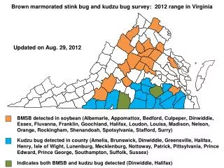
Motivation for the Project • The southern green stink bug is responsible for damaging a variety of crops (cotton, tomatoes, beans, etc...) • They prefer to feed on developing fruits, piercing them and causing them to become deformed and damaged. • It is believed that tracking the stink bugs’ movements through the crop fields can lead to a better understanding of their behaviors and ways to combat them. Southern Green Stink Bug Photo credit: Extension Entomology, Texas A&M University
Unmanned Tracking • The Clemson University Unmanned Aerial Vehicle (UAV) Laboratory has taken an interest in the issue. • Their Goal: to track the movement of stinkbugs through crop fields with UAV on a GPS guided path • Mounting the tracking equipment to the UAV eliminates the need for a large base station in the center of the field • Reduces the range to a predictable value (approximated by the height of the UAV) SR20 Unmanned Aerial Vehicle Photo credit: Clemson UAV Laboratory
How to Track Insects: Harmonic Radar • Most common/successful method currently used today • The most basic system consists of a transmitting antenna, a passive “tag” placed on the object to be tracked, and a receiving antenna • The passive tag requires an antenna and a nonlinear element (diode) at its terminals • The transmit and receive antennas should be mounted on the UAV and the passive tags should be mounted onto the stink bugs
Harmonic Radar Concept • For this analysis, a fundamental frequency of 8.2GHz (“fo”) was chosen to illuminate the tag. • An electromagnetic field incident upon the tag’s antenna will induce a current along its length which will drive the diode at the antenna’s terminals • Due to the non-linearity of the diode, it should produce voltage at harmonic frequencies of the current that is driving it—the largest being at the second harmonic (16.4GHz) • This second harmonic current is then re-radiated through the tag antenna and picked up by the receive antenna • One can differentiate between backscatter from linear elements (ground, foliage, etc.) at “fo” and the backscatter from the tag at “2fo,” thus, locating the insect. fo = 8.2GHz transmit antenna tag antenna diode 2fo = 16.4GHz receive antenna
Basic Tag Design • The basic antenna design is a half-wavelength (of “fo”) dipole trimmed down to a resonant length • At the dipole terminals is a low-barrier beam lead Schottky diode (small in size and high switching speed) • A tuning inductor across the diode “cancels” out the diode’s capacitive reactance at the fundamental frequency • The basic design is simple and elegant, however, improvements can be made to the tag to increase its efficiency and performance. Honeybee Equipped with Basic Tag Photo credit: Rothamsted Research Group
Method of Moments (MoM) Simulation of Basic Tag Antenna • The antenna portion of the tag was simulated in MoM based software. • The MoM software breaks the antenna up into several pieces (small compared to a wavelength) and calculates antenna parameters by summing up the contributions from currents in each of the pieces. Moreover, it’s a numerical solution to an integral equation. • From the simulation we can look at important antenna parameters such as input impedance and far-field radiation patterns Segmented Antenna from MoM Simulator (EZNEC)
Simulation Results at 8.2GHz E-Plane Radiation Pattern Antenna orientation Gain: 2.1 dBi Input Impedance: 72.25 + j 0.14 Ω -3dB Beamwidth: 78.4 deg.
Simulation Results at 16.4GHz E-Plane Radiation Pattern Gain: 3.67 dBi Input Impedance: 414 – j 253 Ω* -3dB Beamwidth: 49.2 deg.* * not desirable
Harmonic Balance Simulation of Tag • It is important to study how power is transferred from the tag’s antenna to the diode (and back to the antenna) • Agilent Advanced Design System (ADS) contains a harmonic balance simulator which is designed to simulate non-linear circuits. • Find a Thévenin equivalent circuit representation of the antenna and run a harmonic balance simulation on the antenna and diode/tuning inductor load.
Thévenin Equivalent for Tag Antenna • Antenna’s input impedance “Ζtotal” can be represented as two series R-L-C networks in parallel. • Tune each series so that “Ζtotal” equals the antenna impedance at both 8.2GHz and 16.4GHz. • Sinusoidal voltage source magnitude is determined by how much power is incident on the antenna. + Ζtotal –
Diode and Tuning Inductor • Diode model was created to represent the Agilent HSCH-5340 low-barrier beam lead Schottky diode • Value of 1.5nH was assigned to the tuning inductor • These elements complete a circuit with the Thévenin equivalent antenna and a harmonic balance simulation can be run on the complete circuit.
Evidence of Power Being Delivered to Antenna at Harmonic Frequencies Spectrum of Magnitude of Vout and I_Probe for Vin = 0.5V The harmonic balance shows the frequency components of the voltage and current between the antenna and the load.
RMS Power Dissipated in Load at 8.2GHz vs. Drive Level *A measure of how well the load is match up to the antenna for receiving power
Second Harmonic Power Delivered to Antenna by Diode vs. Drive Level • There is a certain level (Vin ≈ 0.75 V) where the diode should be driven. • Driving the diode any harder does not result in much more power being delivered back to the antenna. • We should choose a transmitter height/distance and EIRP so that we excited the harmonic tag at a level where Vin ≈ 0.75 V. * Negative values just indicate that power is being supplied rather than dissipated.
Design Improvement:The Trap Dipole • As seen earlier, it is not optimal to re-radiate second harmonic current through a full-wave dipole (narrow beam, high input impedance). • Add parallel L-C networks to the antenna length that resonate at 16.4 GHz • This will result in a high impedance (theoretically ∞ ) at 16.4GHz, “trapping” the 16.4GHz current to the length “a” • 8.2GHz current will see the traps as inductive loads. • Choose length “a” to be that of a half-wavelength resonant dipole at 16.4GHz • Choose length “b” to be that of an inductively loaded resonant dipole at 8.2GHz • A two-band resonant dipole!
MoM Simulation of Trap Dipole • Re-run a MoM simulation on the new design to see how its antenna characteristics compare to the basic design. 8.2GHz Current Sees an Inductively Loaded Dipole Evidence of 16.4GHz Current Being Trapped Between Loads
Simulation Results at 8.2GHz E-Plane Radiation Pattern Gain: 2.14 dBi Input Impedance: 64.9 + j 0.6 Ω -3dB Beamwidth: 78 degrees
Simulation Results at 16.4GHz E-Plane Radiation Pattern Gain: 2.39 dBi Input Impedance: 80.9 + j 1.0 Ω -3dB Beamwidth: 70 degrees
Antenna Comparison • The trap dipole design has more desirable characteristics than the original design for re-radiating second harmonic current • As seen in the previous figure, the radiation pattern is closer to being omni-directional • The input impedance is almost purely real, with a much smaller resistance. One can predict that this will improve power transfer from the load to the antenna at the second harmonic. • Determine a new Thévenin equivalent circuit for the trap dipole design • Run a harmonic balance simulation on the new design to determine if power transfer is truly more efficient/optimal
Harmonic Balance Results and Comparisons A good indication of efficiency.
More Power but Less Gain… Is this Truly an Improvement? • Effective Isotropic Radiated Power (EIRP) - the amount of power that would have to be emitted by an isotropic antenna (evenly distributes power in all directions) to produce the peak power density observed in the direction of maximum antenna gain. • EIRP = (Power)×(Gain)
EIRP Example • 0.428mW of power available at the antenna terminals (to a conjugate matched load) of each design. Powers: Basic Tag: re-radiates 63.2μW (2nd harmonic) Trapped Tag: re-radiates 168 μW (2nd harmonic) Gains: Basic Tag: 3.78dBi 2.388 Trapped Tag: 2.39dBi 1.734 EIRP Basic Tag: 0.151 mW Trapped Tag: 0.291 mW • Although the basic design has a higher broadside gain, the trapped design has nearly twice the EIRP due to its efficient power transfer between the antenna and load!
Predicting the Needed Equipment(transmit tag) • Friis Propagation Equation: • Harmonic Balance predicts desired drive level (gives “Pr”) • MoM simulator gives tag antenna gain “Gr” • Estimate UAV flight altitude (R ≈ 10m) • Choose transmitter power and gain to match this EIRP:
Predicting the Needed Equipment(tag receiver) • Same thing in reverse… • Harmonic Balance predicts second harmonic power delivered to tag (gives “Pt”) • MoM simulator gives tag antenna gain “Gt” • Same UAV flight altitude (R ≈ 10m) • Choose receiver power and gain to match these receive values:
Conclusions • Ultimately an issue of power rather than elegant antenna design • MoM and Harmonic Balance simulators predict power transfer and optimal drive level • Simple improvements to basic design can yield a much more efficient tag • Free space propagation equation predicts necessary tracking equipment
Acknowledgements • My adviser – Dr. Martin • Dr. Noneaker & Dr. Xu • Josh Lawrence • Everyone involved in the SURE lecture/lunch series • My fellow SURE participants


![The southern green stink bug [ Nezara viridula (L.) ] and the brown stink bug](https://cdn1.slideserve.com/2710002/slide1-dt.jpg)