Download
1 / 16
160 likes | 339 Views
Design of an Embedded Radiometer Controller. Elliot Buller Luke Ciavonne Mehdi Mehrpartou. Advisor: Dr. Steven Reising. What is a Water Vapor Profiling Radiometer?. Passive microwave measurement device Measures black body radiation Tuned to resonant frequency of water vapor

E N D
Design of an Embedded Radiometer Controller Elliot Buller Luke Ciavonne MehdiMehrpartou Advisor: Dr. Steven Reising
What is a Water Vapor Profiling Radiometer? Passive microwave measurement device Measures black body radiation Tuned to resonant frequency of water vapor (22.235 GHz) Extremely sensitive to changes in water vapor Can detect water vapor through cloud cover
Applications of Radiometers Forecasting weather Measuring sea surface temperature Cloud cover Precipitation rate Predicting larger regional and global trends Study of atmosphere and surfaces of planets
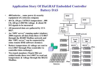
Original Controller System Embedded Intel SBC running Windows 98 Off the shelf boards for data acquisition Custom power conditioning circuit Limitations Prone to failure Power requirements Heat produced
Requirements Low power consumption (<3 Watts) Small Size Reliable Low latency interrupt response Sufficient I/O ports (3 Serial ports, 16 A/D channels)
Our Solution Two board solution: Custom designed 4 layer PC104 daughter card designed by Pat Kusbel ARM9 based commercial single board computer Boards communicate over PC104 bus
Custom Board Hardware 6 Switching Voltage Regulators High Efficiency at High Currents ( > 90%) 7 Linear Voltage Regulators Low Noise (typically 30 μVrms, 10 Hz to 100 kHz) Low Quiescent Current (30 μA) Low Output to Input Ratio for Higher Efficiency
Hardware Verification Procedure DC Voltage Levels Output Voltage Ripple Noise Stability Transient Response Electromagnetic Interference (EMI)
System Diagram Custom board digitizes 4 analog channels from Radiometer ARM9 board initializes and controls custom board Boards communicate with each other over PC104 bus
FPGA ProcessorArchitecture Custom board includes FPGA running Microblazeprocessor Processor tasks include: Periodically polling ADCs Buffering samples on-board Maintain local time-base Control off-board power to radiometer
Microblaze to PC104 Communication Processor clock is faster than PC104 clock Provide temporary storage of data Send periodic interrupt request to trigger data dump to ARM9 board Receive control parameters from ARM9 board
Arm9 Linux Software Linux kernel module Service Interrupts from FPGA SD Card storage daemon Shuttles data from device driver to SD cards Temperature control software Communicates with Peltier unit to control temp within 0.1˚C Time management Communicates with GPS to store and synchronize time on both boards
Next Steps Hardware Finish testing power supplies Run transient analysis on DACs Test all power supplies with dummy loads Software Write time management software to synchronize with GPS Write Microblaze mini-kernel to interface to ADCs Write software to control positioning apparatus Write user interface to configure device and dump data
Thank You Flavio Iturbide-Sanchez OliveraNotaros Dr. Steven Reising SharmilaPadmanabhan Pat Kusbel